
Planning an event in Vivien involves creating a drawing of the venue, complete with all the staging, furniture, decor, A/V equipment, and so on required for the event.
Drawing in Vivien is like drawing in a CAD program, so many of the concepts will be familiar to those who have used a computer-aided drafting program before. Vivien has a comprehensive 3D library containing furniture, equipment, decor items and various human figures—everything you need to plan your event.
In this section
Adding Library objects to your drawing
In Vivien, you do all your drawing in the Drawing Wireframe tab or in the wireframe panes of the Drawing Quad tab.
Vivien drawings use a 1:1, or real scale. When you create a drawing in Vivien, you are generating a virtual representation of your real setup. If you were to do this on paper by hand, you would need to draw a scaled-down version of your space. Because there are no paper size limitations in the drawing wireframe views, you can draw your venue, tables, chairs, trusses, lighting fixtures, and so on in real scale.
You scale your drawing for printing purposes during print set-up and when creating Layouts for printing. The print settings allow you to print your drawings in whatever scales are necessary without having to redraw anything.
You can use either metric or imperial units for measurements.
You can also indicate whether you want:
nImperial units measured in whole numbers or inch fractions (to the sixteenth of a inch). For example, you can specify a measurement of 1’6”3/16, which translates to 1 foot, 6 and 3/16 inches.
nMetric units measured in centimeters or millimeters.
To set the default unit
1In the Drawing Wireframe tab, from the Options menu, choose Document Options.
2Click the Draw Defaults tab.
3In the Measurement Unit section, click either Metric or Imperial.
4Under Precision, select Whole or Fraction.
Whole: The measurements are rounded and displayed to the nearest whole number.
Fraction: The measurements are displayed to the nearest sixteenths of an inch, for Imperial, the nearest millimeter, for Metric.
To change the drawing measurement units
You can change the measurement units on the fly by using the measurement units indicator on the Status bar.
While in any of the tabs, double-click the measurement units indicator (either Metric or Imperial) on the Status bar.
Result: The units instantly change to Metric or Imperial.
When drawing in Vivien Virtual Event Designer you are working in a 3D environment. Objects are drawn as 3D objects, with width, depth and height values based on the Cartesian coordinate system of 3 working axes—X, Y, and Z. The point where the 3 axes meet is called the origin and the values of X, Y, and Z are 0, expressed (0,0,0).
All objects in Vivien Virtual Event Designer occupy three-dimensional space. Different view types allow you to see and work with your drawing from different perspectives.
In Vivien Virtual Event Designer there are six types of wireframe views, each accessible from the View Type toolbar. Each of these views displays the working axes in different ways, as described below.
To switch to a different view type
From the View menu, choose View Type and then select one of the following views:
Plan views display the drawing from above
looking down. This is similar to a plan view drawing on paper. In plan
views, the working axes are X and Y and the Height value
is Z.
Left views display the drawing looking from the left side through the venue. This is similar to a section on paper. In left views the working axes are Y and Z.
Right views display the drawing looking from the right side through the venue. This is similar to a section on paper. In right views the working axes are Y and Z.
Front views display the drawing looking from the front side through the venue. This is similar to an elevation on paper. In front views the working axes are X and Z.
Back views display the drawing looking from the back side through the venue. This is similar to an elevation on paper. In back views, the working axes are X and Z.
A 3D view is a 3D perspective drawing. Although you view the drawing in the 3D perspective while in 3D view, you can only work in two axes. In 3D views, the working axes are dependent on the workplane selected.
To switch to a different workplane in a 3D view
The workplane selected determines the direction in which you can move your cursor in a 3D view. From the View menu, choose Workplane and then select one of the following workplanes:
|
Workplane Plan - The working axes are X and Y. |
|
|
The crosshairs of your cursor change to reflect the selected workplane.
3D view angle
You can rotate the 3D view angle of the 3D view using your keyboard CTRL and arrow keys or CTRL keys and the third mouse button.
When using your mouse, you can also change the rotation speed when you increase or decrease the amount of pixels your mouse needs to travel to rotate the view on the screen using the CTRL keyboard and + or - keys in the keypad.
To rotate the 3D view angle
Hold down the CTRL key and tap the arrow keys on your keyboard.
OR
Hold down the CTRL key, and then click and drag the third mouse button (scroll wheel) towards the direction of the angle change.

Result: The 3D view angle of the 3D view changes according to the direction of the mouse movement.
Tip: If you add SHIFT to either method, the rotation slows down for both keyboard and mouse movement.
Notes:
nRotation direction is determined by the dominant direction of mouse movement. For example, the view rotates in the left - right angle if the mouse is dragged towards the left and slightly up. The view rotates in the up-down angle if the mouse is dragged upwards and slightly left.
nOnce the rotation direction has been determined and the rotation has started, the rotation cannot “switch” to the other direction. You have to release the mouse button and then click and drag again.
To change the mouse cursor speed and travel distance
Press and hold CTRL + SHIFT and tap the + keypad key (i.e. not the + at the top of the keyboard, by the DELETE key) to increase the number of pixels your mouse cursor needs to travel to rotate the view on your screen and slow down the view rotation.
OR
Press and hold CTRL + SHIFT and tap the - keypad key (i.e. not the - at the top of the keyboard, by the DELETE key) to decrease the number of pixels your mouse cursor needs to travel to rotate the view on your screen and speed up the view rotation.
Result:
nThe number of pixels value is displayed on the Status Bar as you increase or decrease with your keyboard keys.
nIt is faster for your mouse cursor to rotate the view when the travel distance is shorter because of the lesser number of pixels set.
nIt is slower for your mouse cursor to rotate the view when the travel distance is longer because of the greater number of pixels set.
Note: 20 pixels is the default number of mouse cursor travel distance.
Use your keyboard and mouse to control the point of view for any of the Vivien views and use the Zoom tools to shrink or enlarge the view on the screen.
Zoom tools allow you to view smaller or larger sections of a drawing. There are seven zoom tools available in Vivien.
To access the Zoom tools
From the View menu, choose one of the Zoom tools.
or
Use the Zoom tools on the View or Layouts View toolbars.
Result: The viewpoint is adjusted accordingly.
The available Zoom tools are listed in the following table:
Zoom tool |
Description |
|---|---|
Zoom In 
|
Moves your viewpoint closer to the center of the view. |
Zoom Out 
|
Moves your viewpoint farther away from the center of the view. |
Zoom Fit 
|
Adjusts the viewpoint so that the extremities of the drawing fit into the current view. |
Zoom Fit All |
For Quad views, adjusts the viewpoint so that the extremities of the drawing fit into the three wireframe views simultaneously. |
Undo View Change 
|
Adjusts the viewpoint so the most current changes to the view are undone |
Redo View Change 
|
Adjusts the viewpoint so that any changes to the view caused by Undo View |
Zoom Window 
|
Allows you to specify the area of the drawing to be viewed. For more information on using this tool, refer to the procedure below. |
To use the Zoom Window tool
1From the View menu, choose the Zoom Window tool.
2Click the left mouse button and drag a window around the area into which you want to zoom.
3Click the left mouse button again to capture the second point of the window.
Result: The view changes to amplify the area you selected.
Rotate tools allow you to shift 3D and Virtual Views left, right, up, or down.
To access the Rotate tools
In Vivien Designer, while in a 3D or Virtual View, from the View menu, choose Rotate View, and then choose one of the Rotate commands.
or
Use the Rotate tools on the View or Layouts View toolbars.
Result: The viewpoint is adjusted accordingly.
The available Rotate tools are listed in the following table.
Rotate tool |
Description |
|---|---|

Rotate View Left |
Moves your viewpoint to the
left. |

Rotate View Right |
Moves your viewpoint to the right. |

Rotate View Up |
Moves your viewpoint up. |

Rotate View Down |
Moves
your viewpoint down. |
To modify the point of view
Action |
Key or mouse movement |
|---|---|
Move the view left, right, up and down |
Left, right, up and down arrow keys, respectively |
Zoom in and out |
PAGE UP and PAGE DOWN keys, respectively or Roll middle mouse button up and down. The zoom action is centered on the mouse pointer, not the center of the window. |
Rotate the view (3D perspective—3D or Virtual View only) |
Hold down the CTRL key and use arrow keys or PAGE UP and PAGE DOWN keys. |
Move the drawing around the window (pan) 
|
Hold down the middle mouse button and drag. or Use the Pan tool
on the View toolbar. |
nAt any time you can press SHIFT in combination with any of the movement keys to move in smaller increments.
nIn Virtual Views, you can use the mouse instead of the aforementioned key strokes. Click and drag to pan around and use the mouse wheel for zooming.
Camera control in Virtual View
By default, Traditional Vivien is the camera control setting in the Virtual View where the mouse and keyboard action commands are standard Vivien commands used in all version of Vivien.
In the Application Options window, you can choose the Other 3D Applications on the Virtual View Camera Control drop-down if you want to use camera control that comply with other 3D applications. See “Camera Control” for alternative mouse and keyboard action commands.
To begin your drawing, you need to define the venue, the physical space where your event will take place. You set the dimensions of the space and Vivien draws the 2D or 3D plan for it, defining where the walls, floors, and ceilings are.
After you draw the venue, you can apply either a custom color or texture to each part of it; you can also apply a custom material to selected parts of the venue, if desired. For details, see “To apply custom material, and color or texture to a venue”.
You can define the following types of venues:
nroom
narena
ntheatre
nframe tent or circus tent
For details on each type of venue, see the appropriate section below.
A room venue is an empty rectangular room. The origin is at the center of the room on the floor.

|
Description |
New Venue- Room Field |
Vivien Default Value |
|---|---|---|---|
A |
Width of the room |
Width |
40’0” |
B |
Depth of the room |
Depth |
80’0” |
C |
Height of the room |
Height |
20’0” |
An arena venue is a basic stadium space. The following entries describe the parts of the arena. The origin is at the center of the venue on the floor or ice rink.

|
Description |
New Venue- Arena Field |
Vivien Default Value |
|---|---|---|---|
A |
Width of the arena |
ARENA Width |
170’0” |
B |
Depth of the arena |
ARENA Depth |
250’0” |
C |
Total height of the arena |
ARENA Height |
60’0” |
D |
Width of the floor or ice rink |
FLOOR Width |
60’0” |
E |
Depth of the floor or ice rink |
FLOOR Depth |
130’0” |
F |
Height
of the stands or seating |
STANDS Height |
40’0” |
A theatre venue is a basic theatrical space with a stage, proscenium arch, and an auditorium. The origin is at the intersection of the center line and the proscenium line on the stage floor.

The following entries describe the parts of the theatre.
|
Description |
New Venue - Theatre Field |
Vivien Default Value |
|---|---|---|---|
A |
Stage width |
STAGE Width |
90’0” |
B |
Stage depth |
STAGE Depth |
50’0” |
C |
Stage height |
STAGE Height |
4’0” |
D |
Thrust depth |
STAGE Thrust Depth |
8’0” |
E |
Thrust width |
STAGE Thrust Width |
35’0” |
F |
Fly height |
STAGE Fly Height |
60’0” |
G |
Proscenium arch width |
ARCH Width |
40’0” |
H |
Depth of the proscenium arch wall |
ARCH Depth |
2’0” |
I |
Height of the proscenium arch
|
ARCH Height |
20’0” |
J |
Back of house (BOH) width |
AUDITORIUM |
100’0” |
K |
Auditorium depth |
AUDITORIUM |
100’0” |
L |
Auditorium height |
AUDITORIUM |
45’0” |
M |
Front of house (FOH) width |
AUDITORIUM |
68’0”. |
N |
Auditorium slope height |
AUDITORIUM |
12’0” |
Aside from the selection of ready-made tents that come with Vivien (in the library on the Architecture tab), there are two types of tents that you can create yourself—frame tents and circus tents.
nFrame tents: These tents are square or rectangular in shape and usually have two center poles. Each wall is made of a single piece of fabric supported by as many poles as you specify.
nCircus tents: These tents are styled after the classical “Big Top” of the circus. They are more rounded in shape than the frame tent, the walls comprising multiple sections, each supported by as many poles as you specify. The roof is held up by one center pole.
When drawing either type of tent, you can specify many different properties, including the number of poles, length, height, or perimeter of the walls, and the color of different parts of the tent.
You can also choose from different materials and you can choose whether you want to apply either a custom color or texture to different parts of the tent. When assigning a texture, you can choose your own texture, such as a company logo or symbol, or you can choose a texture from the Vivien library.
The origin for both types of tents is at the center of the tent on the floor.
Frame tent

The following entries describe the parts of the frame tent:
|
Description |
New Venue - Tent Field |
Vivien Default Value |
|---|---|---|---|
A |
The height of the tent walls. |
Wall height |
20’0” |
B |
The width of the tent walls (in a rectangular tent, this is the longer side of the rectangle). |
Width |
80’0” |
C |
The depth the tent walls (in a rectangular tent, this is the shorter side of the rectangle). |
Depth |
70’0” |
D |
The amount that the center pole extends above the height of the walls. |
Height above walls |
10’0” |
E |
The distance between the center poles. |
Separation |
20’0” |
Circus tent

The following entries describe the parts of the circus tent:
|
Description |
New Venue - Tent Field |
Vivien Default Value |
|---|---|---|---|
A |
The number of individual segments in the tent. |
Segments |
6 |
B |
The height of the tent walls. |
Wall height |
20’0” |
C |
The amount that the center pole extends above the height of the walls. |
Height above walls |
10’0” |
D |
The diameter of the tent, measured from pole to opposite pole. |
Diameter |
70’0” |
Note: For help on any of the boxes in the venue windows, click the Help question mark icon, and then click in the applicable box.
1From the Draw menu, choose Venue, and then select Room, Arena, Theatre, Frame Tent, or Circus Tent.
Result: Based on the type of venue that you have chosen, a different dialog box opens in which you can modify the properties of the venue. The following graphic shows the New Venue - Arena dialog box:

2Modify the properties, and then click OK.
Result: A view-only framework for the selected venue displays in the drawing.
1Click on a venue line to select the venue.
2Right-click and select Object Properties.
Result: The Properties dialog box displays.
3Click the venue tab (for example, Room).
4Make the necessary changes, and then click OK.
Tip: To make the venue uneditable so that you do not accidentally move it while working on your drawing, click the Layers tool. In the Layer Database window, highlight the Venue line, and then clear the check mark beside Editable. Click OK.
To apply custom material, and color or texture to a venue
Once you have drawn your venue, you can customize it by applying either color or texture, and a custom material to each of its structural elements, such as walls, ceiling, and floor. Based on the type of venue, you can also change the properties of the structural elements themselves. For example, for a tent you can change the wall height, the number of poles, the visibility of its walls, and so on.
Note: The following procedure uses the example of a tent; however, you can perform the same procedure for other types of venues, such as rooms and theatres, changing the applicable elements for each type of venue.
1Click the Drawing Wireframe tab.
2Click the venue to select it. In this example, click the tent.
3Right-click, and then select Object Properties.
Result: The Properties dialog box displays.
4To change structural elements, click the applicable venue tab (in this example, Frame Tent). For tents, you can change elements such as the size, number of poles, and visibility of walls and poles.
5Make the necessary changes, and then click Apply.
6Click the Appearance tab.
7Within the Elements box, click to highlight the first venue element that you want to customize or edit (for example, Walls). To select multiple elements and apply the same customization to all of them at once, press CTRL and select the applicable elements. Proceed with any of the following steps to customize the element:
To apply custom color to the venue element
When customizing a venue, you can choose either a color or a texture for the selected venue elements, you cannot choose both. The default color for the element is the current layer’s rendering color.
a.After performing steps 1 to 7 above, click to select the Custom Color option button.
b.Click the color box and, in the resulting dialog, select the desired custom color.
c.Click OK.
d.Click Apply.
To apply a custom texture from the Vivien library to the venue element
When customizing a venue, you can choose either a color or a texture for the selected venue elements, you cannot choose both.
a.After performing steps 1 to 7 above, to apply a texture from the Vivien library to the tent element, click the Texture from Library option button.
b.In the resulting dialog, navigate to and select the desired texture, and then click Select.
c.To have the texture repeated over the selected element in a continuous series of squares or rectangles, click the Tile option button, and then type the size of the frame in which you want the texture to appear in the Width and Height boxes. Based on the size that you enter, Vivien calculates how many times the texture is repeated (or tiled) to completely cover the selected tent element.
d.To have the texture stretch over the entire element surface, click Stretch.
e.To preserve the aspect ratio of the texture so it is not distorted when stretched over the element, click Keep Aspect Ratio.
f.To choose a custom border color for the texture when it is stretched over the surface of the element, click the Border Color box, and then choose the custom color.
g.To adjust the angle at which the texture is shown, select the value from the Texture Rotation Degrees drop-down box.
h.Click Apply.
To apply an image source as texture to the venue element
a.After performing steps 1 to 7 above, to apply your own texture to the tent element, click the Image Source option and select from the drop-down or click New.
Result: The Image Manager opens if you clicked on New.
b.In the Image Manager window, you can add images as sources and modify their properties. See “Using the Image Manager”.
Or you may proceed to the next step if you have selected an image from the drop-down list.
c.To have the texture repeated over the selected element in a continuous series of squares or rectangles, click the Tile option button, and then type the size of the frame in which you want the texture to appear in the Width and Height boxes. Based on the size that you enter, Vivien calculates how many times the texture is repeated (or tiled) to completely cover the selected tent element.
d.To have the texture stretch over the entire element surface, click Stretch.
e.To adjust the angle at which the texture is shown, type or select from the Rotation (Deg.) drop-down box.
f.Click Apply.
To apply custom material to the venue element
a.After performing steps 1 to 7 above, click the ellipsis button (...) under the Material Properties section.
b.In the resulting dialog, navigate to and choose your custom material.
c.Click Select.
d.On the Appearance tab, click Apply.
To apply transparency to the venue element
a.After performing steps 1 to 7 above, to apply a transparency level to the color or texture that you have chosen for the element, or to override the default transparency level of the selected material click either of the following option buttons:
nMaterial Properties: Click the ellipsis button (...) to choose a material for the selected elements. Click Default to remove the selected material from the element and return to the default material.
nMaterial: When a material is selected, the properties of the material will vary from one material to the next. The Material Properties section enables these default material settings to be changed. Each property value can be changed on a scale from 0%-100%. An explanation of the value is found on the right side of the property.
nTransparency: This setting controls the proportion of light that passes through the material. 0% being completely opaque, 100% being completely clear.
nSpecular Level: This setting controls how prominent other specular effects appear on the material. 0% being no visibility of specular effects, 100% being a maximum visibility of specular effects.
nSpecular Gloss: This setting controls the level of gloss a material will project. 0% will project the gloss over a wide area, 100% will concentrate the gloss in a small area.
nSpecular Color Source: This setting controls the color of light projected on a material. 0% will show only the color of the light, 100% will show only the color of the material.
nLight Reflection: This setting controls the amount of light that is reflected off the material. 0% having no reflection, 100% being specular.
nDisplay Reflection in Virtual Views: This setting controls whether true reflections are show by the object’s material in Virtual Views.
8Click OK when you are finished.
To draw a custom room
1From the Draw menu, choose Room Builder.
Result: A cross-hair will appear on your cursor in the drawing wireframe.
2Click to place a corner of the wall at the location of the cursor. Each subsequent click will connect the current corner to the previous corner.
3To finish the room drawing as is, right-click and select Finish Room Outline.
Note: Alternately, the room can be closed, connected the first and last created corner automatically, by right-clicking and selecting Close Room Outline.
Result: The Room Builder window will appear.

4In the Room Builder window, enter in the missing characteristics of the room walls.
5Select the Place Wall object on opposite side of the Room Outline checkbox if you want to place object on the opposite side of the room outline.
6Select the Close Room outline checkbox if you want to add floors or ceilings to the room.
Note: This option is only available if the room is closed. When a room is closed, Vivien automatically makes the Walls transparent from outside of the room looking inwards, and makes the ceiling and floor single sided, so when the camera is outside of the room the user can see inside. These properties can be changed if the user wishes, by going to the objects' properties
a.Select the Add Floor checkbox to add a floor to the room.
b.Select the Add Ceiling checkbox to add a ceiling to the room.
7Click Enter.
Result: The custom room will be created in Vivien.

If you have an existing floorplan saved in a graphic format like such as bitmap (.bmp), JPEG (.jpg), PNG (.png), PDF (.pdf) or .gif, you can import it into your Vivien drawing, and then continue to customize it within Vivien by adding tables, chairs, and so on to it.
You can import floorplan images in 3 view types:
nPlan: Floorplan images in Plan view can be imported into the Drawing Wireframe tab that is set to Plan View Type.
nFront/Back: Floorplan images in Front or Back profile views can be imported into the Drawing Wireframe tab that is set to the Front or Back View Type.
nLeft/Right: Floorplan images in Left or Right profile views can be imported into the Drawing Wireframe tab that is set to the Left or Right View Type.
Notes:
nYou can print with Imported Floorplans in Wireframe and Layouts.
Attention: Imported floorplans are a purely visual feature without any guarantee of accuracy and precision in the printed document. When printing a floorplan, a Warning dialog appears asking for you to acknowledge that there are no guarantees about the content, accuracy, precision, or anything else in the printed document and that you will not hold CAST responsible for any errors or inaccuracies in the document. Select the checkbox and click OK to proceed.

nThe images in the profile views allow you to import wall outlines for the room that you are building in your 2D drawing.
To import a floorplan
Note: Before you perform this procedure, you must know the precise dimensions of at least one of the elements in your imported floorplan. For example, if it contains a stage, note the width of the stage before you import the graphic into your Vivien drawing.
1In the Drawing Wireframe tab, in Plan view, click File > Import Floorplan... > Plan.
or,
In Front or Back view, click File > Import Floorplan... > Front/Back.
or,
In Left or Right view, click File > Import Floorplan... > Left/Right.
Result: The Floorplan Importing Wizard window will appear.

2In the window click Browse.
Result: The file browser window will open.
3In the file browser window, navigate to your floorplan image, select it, and then click Open.
Result: The file browser window will close. The location of the floorplan image will be in the Browse field.
4Click Next.
Result: The wizard will switch to the Rotate Floorplan page. Here the floorplan image can be rotated 0°, 90°, 180° or 270°.

5Select the angle of rotation for the floorplan, then click Next.
Result: The wizard will switch to the Define Anchor Point page. You can select from predefined anchor points or create your own.

6From the Anchor drop-down menu, select the anchor point of the floorplan.
a.If a custom anchor point was selected, click a point in the floor plan to create the anchor point.
7Click Next.
Result: The wizard will switch to the Define Insertion Base Point page. The anchor can be inserted at either the origin or a user selected point.

8Define the insertion base point, then click Next.
a.If a user selected point was chosen, the wizard window will minimize. Click on a point in the Vivien file where you want the insertion point to be.
Result: The wizard will switch to the Specify Floorplan Scale page. Here a dimension line is drawn between two points of the floorplan to determine its scale.

9Ortho X and/or Ortho Y can be enabled to ensure any dimension line drawn is parallel with the respective axis.
Note: This step can be skipped if you are modifying a previously imported floor plan, by selecting the box next to Skip this Step....
10Click Next.
Result: The window will minimize and show the floorplan inserted into Vivien.
11In the floorplan image, choose an item in your drawing whose measurements you know, and then click on one end of the item. For example, if you know the dimensions of the Stage, click on one corner of it.
12Click on a opposite end of the item. For example, if you had clicked on one edge of the table, click on an opposite edge of it.

Result: The Import Floorplan window will reappear, prompting you to enter the length of the line that you have just drawn.

13Type the length of the line, and then click Next.
Result: Vivien adjusts the size of the floorplan based on the scale that you have entered to ensure that your drawing is accurate. The floorplan appears in your drawing in plan view (the only view in which you can see it).
14Click Finish to finish editing the floorplan. Click Back to change any of the previous settings.
Tip: Once you import the floorplan, you can hide it from sight by right-clicking on your drawing and selecting Hide Floorplan. To show the floorplan again, simply right-click and select Show Floorplan.
Tip: To modify the properties of the floorplan after it has been inserted, right-click the floorplan image and select Modify Floorplan.
Note: You can delete floorplans, but once deleted, the floorplan must be re-imported in order for it to be available once again. Since this process may affect the measurements set in the above procedures, it is recommended that you only delete floorplans once everything is finalized.
To delete a floorplan
If you have imported a floorplan into your Vivien document, and then want to remove it, you can delete it from the file.
1In the Drawing Wireframe tab, in Plan view, right-click on your event drawing and select Delete Floorplan.
Result: The floorplan is deleted.
You draw objects in drawing wireframe views (the Drawing Wireframe tab and additionally, in Vivien Virtual Event Designer, the Drawing Quad tab). The Draw menu lists the objects that you can draw.
Keep the following tips in mind when you are drawing objects:
nAt any time, instead of clicking points with the mouse, you can type in the desired coordinates. See “Command line”.
nCreate shortcuts for library objects. See “Shortcut bars”.
nUse the Height value in Vivien Virtual Event Designer. “The Height value”.
nUse keyboard shortcuts and hot keys. See “About keyboard shortcuts and hotkeys”.
nBefore you place a 2D/3D primitive object, screen, or LED wall into your drawing, you can right-click on the object and select its Insertion Point from the menu that appears. See “Insertion points” for details.
Points identify specific coordinates in 3D space. You can insert points as references or as scenic elements. There are four different point styles: dot, cross, square, and circle. The default point style is defined for the document.
To draw a point
1From the Draw menu, choose Point.
or
Click the Point tool on the Draw toolbar.
|
The Point button. |
2Click on the drawing to place the point.
For information on modifying a point once you have drawn it, see “Point tab”.
Lines are 2D objects that join vertices. In Vivien, you can draw lines continuously, which means you can easily join multiple vertices to create shapes.
nSolid
nCenter
nDashed
nDot
Line styles determine how line objects appear on your drawing and can be modified at any time.
Line patterns are available to a Rectangle, Circle, Ellipse, Arc, and Elliptical Arc.
You can 3D Transform lines into surfaces. For more on transforming lines, “Transforming objects into surfaces or 3D surfaces”.
When you draw multi-segmented lines, or add a line to a surface, or when drawing a room using the Room Builder, the next point of the line you wish to add snaps automatically to the previously drawn line/surface’s endpoint, midpoint or intersection when the Endpoint Snap, Midpoint Snap and/or Intersection Snap are enabled.
1From the Draw menu, choose Line.
2From the sub-menu, select Solid, Dot, Center, Dashed.
Tip: You
can also use the appropriate line tool on the Draw toolbar.
The available line tools are as follows:
n ![]() Solid
Solid
n![]() Dot
Dot
n![]() Center
Center
n![]() Dashed
Dashed
3Click on the wireframe at the starting point of the line.
4Drag the next vertex to its end point and click.
5Continue to place vertices of the line as needed on and click.
6Continue to place vertices as needed.
7To end the line at the last vertex you placed, right-click and choose Finish Line.
To cancel the drawing of the line, right-click and choose Abort Line. This erases the entire line from the drawing.
To join the last point you placed with the first one you placed, right-click and choose Close Line.
To draw a line by specifying coordinates
You can also draw lines using coordinates by specifying absolute or relative values.
1From the Draw menu, click Line and choose Solid, Dot, Center or Hidden.
2In the Command Line, type the absolute X, Y and Z coordinates (separated by commas) where you want the line to start (i.e. @0,0,0).
3Press ENTER to establish the first point of the line.
4In the Command Line, type the absolute X, Y, and Z coordinates where you want the next point of the line or,
Using the relative values, in the Command Line, type @, followed by the length towards the next point of the line (positive or negative direction), (i.e. @3’6”,0,3’).
5Press ENTER to draw the new line segment.
6Continue to type absolute or relative values and press ENTER to draw the next line segments.
7When you are finished drawing the lines, right-click and click Finish Line.
To draw a line by specifying its length and angle
1From the Draw menu, click Line and choose Solid, Dot, Center or Hidden.
2In the Command Line, type the X, Y, and Z coordinates (separated by commas) where you want the line to start (i.e. @ 0,0,0).
3Press ENTER to establish the first point of the line.
4In the Command Line, type the length towards the next point of the line followed by the < sign and the angle (direction), (i.e. @3’6”<-180).
5Press ENTER to draw the new line segment.
6Continue to type the length and angle in the Command Line.
7When you are finished drawing the lines, right-click and click Finish Line.
Tip: You can also determine the direction of the line from the cursor’s current position relative to the start point set in step 2.
For information on modifying a line once you have drawn it, see “Line tab”.
Splines are curved lines that pass through multiple vertices that influence the shape of the curve (or french curve).
To draw a Spline
1From the Draw menu, choose Spline.
Tip: You can also use the appropriate spline tool on the Draw toolbar.
|
The Spline button. |
2Click on the drawing at the starting point of the spline.
3Drag the next vertex to its end point and click.
4Continue to place vertices of the spline as needed and click.
5Continue to place vertices as needed.
6To end the line at the last vertex you placed, right-click and choose Finish Line.
Right-click and choose Abort Line to cancel the drawing and erase the entire spline.
There are two ways to draw circles:
nSpecify the horizontal and vertical radius and place the circle in the drawing.
nDraw the circle freehand.
To draw a circle
1From the Draw menu, choose Circle.
or
Click the Circle tool on the Draw toolbar.
|
The Circle button. |
Result: The New Circle dialog box opens.
2In the Horizontal Radius box, type the horizontal radius for the circle. The default value is 4’0”.
3In the Vertical Radius box, type the vertical radius for the circle. The default value is 4’0”.
Note: When the Horizontal and Vertical radii are the same, a circular object is created; when they are different, the object is oval-shaped.
4To ensure that the circle remains proportionately the same when resized, leave the Lock Ratio checkbox checked. If you clear this checkbox, then you can manually resize the circle in any direction, regardless of its original measurements.
5Click OK.
6Click in the drawing to place the circle.
To draw a circle in Freehand mode
1Switch to Freehand mode, if you are not already in it, by clicking the Freehand Mode tool on the Tools toolbar.
|
The Freehand Mode button. |
2From the Draw menu, choose Circle.
or
Click the Circle tool on the Draw toolbar.
|
The Circle button. |
Result: The New Circle dialog box opens.
3Click to place the center of the circle.
4Click to set the radius for the circle.
There are two ways to draw an arc:
nSpecify the arc radius, start and end angles and place the arc in the drawing.
nDraw the arc freehand.
To draw an arc
1From the Draw menu, choose Arc.
or
Click the Arc tool on the Draw toolbar.
|
The Arc button. |
Result: The New Arc dialog box opens.
2In the Radius box, enter a radius for the arc. The default value is 4’0”.
3In the Start Angle box, enter the start angle. The default value is 0.00.
4In the End Angle box, enter the end angle for the arc. The default value is 180.00.
5Click OK.
6Click on the drawing to place the arc.
To draw an arc in Freehand mode
1Switch to Freehand Mode, if you are not already in it, by clicking the Freehand Mode tool on the Tools toolbar.
|
The Freehand Mode button. |
2From the Draw menu, choose Arc.
or
Click the Arc tool on the Draw toolbar.
|
The Arc button. |
3Click to place the start point of the arc.
4Click to place the end point of the arc.
5Click to place the middle point of the arc.
There are two ways to draw an arc:
nSpecify the elliptical arc radius, start and end angles and place the arc in the drawing.
nDraw the elliptical arc freehand.
To draw an elliptical arc
1From the Draw menu, choose Elliptical Arc.
or
Click the Arc Elliptical tool on the Draw toolbar.
|
The Arc Elliptical button. |
Result: The New Elliptical Arc dialog box opens.
2In the Radius box, enter a radius for the elliptical arc. The default value is 4’0”.
3In the Start Angle box, enter the start elliptical angle. The default value is 0.00.
4In the End Angle box, enter the end angle for the elliptical arc. The default value is 180.00.
5Click OK.
6Click on the drawing to place the elliptical arc.
7Click and drag the mid point of the arc to create the desired elliptical
To draw an arc in Freehand mode
1Switch to Freehand Mode, if you are not already in it, by clicking the Freehand Mode tool on the Tools toolbar.
|
The Freehand Mode button. |
2From the Draw menu, choose Elliptical Arc.
or
Click the Arc Elliptical tool on the Draw toolbar.
|
The Arc Elliptical button. |
3Click to place the start point of the elliptical arc.
4Click to set the horizontal and vertical radii of the elliptical arc.
5Click to set the start point of the ellipse.
6Click to set the end point of the ellipse.
There are two ways to draw rectangles:
nSpecify the length and width and place the rectangle in the drawing.
nDraw the rectangle freehand.
To draw a Rectangle
1From the Draw menu, choose Rectangle.
or
Click the Rectangle tool on the Draw toolbar.
|
The Rectangle button. |
Result: The New Rectangle dialog box opens.
2In the Length box, type the length for the rectangle. The default value is 4’0”.
3In the Width box, type the width for the rectangle. The default value is 8’0”.
4To ensure that the rectangle remains proportionately the same when resized, leave the Lock Ratio checkbox checked. If you clear this checkbox, then you can manually resize the rectangle in any direction, regardless of its original measurements.
5Click OK.
6Click in the drawing to place the rectangle.
To draw a Rectangle in Freehand mode
1Switch to Freehand mode, if you are not already in it, by clicking the Freehand Mode tool on the Tools toolbar.
|
The Freehand Mode button. |
2From the Draw menu, choose Rectangle.
or
Click the Rectangle tool on the Draw toolbar.
|
The Rectangle button. |
3Click to place one corner of the rectangle.
4Click to place the opposite corner for the rectangle.
Shapes are regular shaped objects comprising multiple vertices. You can draw Shapes as 2D objects or specify a height to create 3D objects. You can use shapes to create either wireframe or solid objects.
Unlike the Surface tool, the Shape tool gives you the ability to quickly and easily create symmetrical shapes like squares, pentagons, hexagons, hectagons, and so on. The maximum number of edges that a shape can have is 40.
Note: Unlike most other tools, the Shape tool does not have an interactive mode.
To draw a shape
1 From the Draw menu, choose Shape.
|
The Shape button. |

2In the Number of Edges box, type the number of edges or sides of the shape.
3Specify the Radius (the distance from the center of the shape to the nearest vertex).
4Click Height if you want to extrude the shape into a 3D object, and then type the height value in the box provided.
5Click OK to place the shape in your drawing.
Text labels enable you to label different parts of your drawing for your reference. The labels only appear in wireframe views and the 3D View.
To change the Text Label font globally
You can specify the font that you would like to appear globally in all text labels, both new and existing.
1In any drawing mode, click Options > Document Options.
2Click the Font tab.
3Under Text Labels (Drawing Wireframe), from the Font drop-down list, select the font that you want to appear in all new text labels.
4Choose whether you want the letters to appear bold, underlined, or in italics.
5Click OK.
To draw a text label
1From the Draw menu, choose Text Label.
Tip: You can also use the Text Label tool on the Draw toolbar.
|
The Text Label button. |
Result: The New Text Label window will appear.

2In the New Text Label window, in the Text box, type the desired text.
Note: Use SHIFT+ENTER to add new text lines.
Tip: You can also type text labels with information listed in the Event Info table using smart variables %Variable Name% in New Text Label. The information will be displayed automatically. For example, use %Director% and the name of the Director stored in the table will appear in the Text Label.
3Click Insert Smart Variable to open the Smart Variables window where you can select the smart variable names and values that are listed in the Event Info tab in Document Options.
Result: The Smart Variables window appears.

a.From the table in the Smart Variables window, click on the name, translated name, or value that you want to insert in the text box.
Tip: Click the Filter drop-down and choose which information to display in the table. See “Event Info tab”.
b.Select the Include Name and Value checkbox to display both texts under the name and value columns, or you can leave the checkbox clear to display only the texts under the value column.
c.Click Insert.
Result: The smart variable text appears in the Text box of the New Text Label window.
4Using the radio buttons, choose how you want to specify the Height of the Text Label, and enter the value in the corresponding field.
nIndividual Line of Text - Each line of text will be the chosen height. The text label will change size to accommodate the height.
nTotal Text Label - The total text box will be the chosen height. Text will change size to accommodate the height.
a.To add space between the text and the boarder of the text label, select the checkbox next to Text Label Padding, and enter the value of the padding in the field.
Note: The Total Text Label Height field will tell you the exact height of the text label based on your choices.
5To add a callout to the text label, select the Show Callout checkbox.
a.From the Position drop-down menu, select where the callout will be located on the text label.
b.To have an arrow at the end of the callout, select the Show Arrow checkbox.
6To add a border to the text label, select the Show Border checkbox.
7To fill the text label with color, select the Fill checkbox.
a.Click the Color Selector button to choose the color that will fill the text label.
8To align the text label to the current view, select the Align to View checkbox.
9To insert the text label, click OK.
Result: The New Text Label window will close and you will be in the Wireframe view.
Note: If the Callout checkbox was selected in the New Text Label window, the first click in Wireframe view will be the arrow's position, and the second position will place the text label.
10Click on the drawing to place the text label.
Result: The text label will be placed.

Notes:
nTo change the font of existing text labels in wireframe modes, see “ To change the font of Text Labels ” below.
nThe insertion point for the text label is at the intersection of the crosshairs.
To change the font of Text Labels
To change the font of existing labels, you must do so individually through the label’s Properties window.
1Select the text label whose font you want to change.
2Right-click, and then choose Object Properties.
3Click the Text Label tab.
4Under Font, clear the checkbox beside Use Document Defaults.
5From the Font drop-down list, select the new font.
6Choose whether you want the letters to appear bold, underlined, or in italics.
7Click OK.
To set alignment for a text label
1Select the text label for which you want to change the alignment.
2Right-click and choose Object Properties.
3Click the Text Label tab.
4Set the horizontal and vertical justification as desired.
5Select the Align to View checkbox to ensure the text label is legible in all view types (plan, left, right, front, back, and 3D).
6Click OK.
Result: The text label relocates around the insertion point based on the options selected.
Dimensions are 2D objects that help you measure different aspects of your drawing. There are several types of dimensions that you can draw in Vivien:
|
Linear dimension lines. |
|
Continue dimension lines. |
|
Baseline dimension lines. |
|
Arc length dimensions. |
|
Radial dimensions |
|
Angle dimensions |
|
Linear scale |
You can also use the angle dimension tool to define precise angles in your drawing, which helps when verifying angular measurements, and can act as a guide for the drawing process.
Dimension lines are 2D objects that measure and display the distance between two points based on the selected measurement mode. The measurement mode describes which axis the distance is measured along.
nIn Vivien Virtual Event Designer, the measurement modes available are: X, Y, XY, XZ, YZ and XYZ.
For example, in an XY plane, the X measurement between two points is the distance along the X axis between the two points, as shown in the following picture.

The dimension is visible only in one view type. The view type is set when the dimension is drawn and is dependent on the view type and workplane in which the dimension is drawn.
To draw a linear dimension
1From the Draw menu, Dimensions sub-menu, choose Linear Dimension.
Tip: You can also click the Linear Dimension tool on the Draw toolbar.
|
The Linear Dimension button. |
2Click on the drawing to set the dimension start point.
3Right-click to set the measurement mode.
Tip: In measurement mode, you can choose Multiple, which enables you to draw multiple Linear Dimensions, using the last point of the previous measurements as the initial point for the next measurement.
4Click on the drawing to set the dimension end point.
5Click and drag the grab point in the center of the dimension text to drag the text to the correct side of the object, if required.
6Click to set the dimension line.
Tips:
nUse snaps to connect dimensions directly to other objects.
nYou can set the rotation angle of the Linear Dimension to rotate the extension lines around the dimension end points. The rotated Linear dimension will then display the distance between the two points at the angle specified. Right-click on the Linear Dimension and select Object Properties.
nYou can change the Fill color behind the dimension text of the Linear Dimension. Right-click on the Linear Dimension and select Object Properties.
nYou can select Display Dash in Document Options > Dimensions tab to display the linear dimensions with a dash between foot and inches in imperial measurements (e.g. 19’-3 11/16”).
nTo change the font used in all dimensions, click Options > Document Options > Fonts. In the Dimensions (Drawing Wireframe) section, select the font options to be used in all dimensions.
Continue dimensions display sequential chains of linear measurements that are aligned to the start (base) measurement of the Continue Dimension, always using the last point of the previous measurement as the initial point of the next measurement.
To draw a continue dimension
1From the Draw menu, Dimensions sub-menu, choose Continue Dimension.
Tip: You can also click the Continue Dimension tool on the Draw toolbar.
|
The Continue Dimension button. |
Note: You can also start the Continue Dimension on an existing Linear Dimension.
2Click on the drawing to set the dimension start point.
3Click on the drawing to set the next point and direction of the subsequent measurements in the Continue Dimension.
4Repeat setting the next point and direction to continue on the subsequent dimensions.
5Right-click on the drawing to set the dimension end point.
Note: After completing a Continue Dimension, the measurements created are individual Linear Dimensions.
Example: Continue Dimension

Baseline dimensions display linear measurements stacked above or below the Base Dimension while maintaining uniform spacing between, always using the first click as the initial coordinate for all subsequent measurements.
To draw a baseline dimension
1From the Draw menu, Dimensions sub-menu, choose Baseline Dimension.
Tip: You can also click the Baseline Dimension tool on the Draw toolbar.
|
The Baseline Dimension button. |
2Click on the drawing to set the dimension start point.
3Click on the drawing to set the end point of the first Baseline Dimension.
4Click on the drawing to set the position (above or below) for the next/subsequent Baseline Dimension.
5Click on the next point to complete the next Baseline Dimension measurement, and set the direction of the subsequent measurement.
6Repeat setting the next point to create the subsequent Baseline Dimensions.
7Right-click on the drawing to set the dimension end point.
Note: After completing a Baseline Dimension, the measurements created are individual Linear Dimensions.
Example: Baseline Dimension

The arc length can be displayed for any arc drawn in the Drawing Wireframe/Quad. Once enabled, the arc length dimension is attached to the arc and automatically updates itself whenever the arc is changed. The dimension is only visible in the view type in which it was drawn. Although the arc length dimension is attached to the arc, it is a separate entity. Each arc length is individually selectable and has its own properties. Arc length dimensions can be separated onto their own layers, and given their own colors and line weights.

To draw an arc length dimension
1In a Drawing Wireframe, select the arc for which you want to display an arc length dimension.
2From the Draw menu, Dimensions sub-menu, select Arc Length Dimension.
Tip: To adjust the font used in all dimensions and with the Angle Dimension tool, click Options > Document Options > Fonts. In the Dimensions (Drawing Wireframe) section, select the font options to be used in all dimensions and with the Angle Dimension tool.
The radius of a circle/arc is defined as the distance from the center of a circle/arc to its perimeter. The radius can be displayed for any circle or arc drawn in the Drawing Wireframe/Quad tabs. Once enabled, the radial dimension attaches to the circle/arc and automatically updates itself whenever the circle/arc is changed. Note that the dimension is only visible in the view type in which it was drawn. Although the radial dimension is attached to the arc, it is a separate entity with its own properties and can be individually selected. Radial dimensions can be separated onto their own layers, and given their own colors and line weights.

To draw a radial dimension
1In Drawing Wireframe, select the circle/arc for which you want to display a radial dimension.
2From the Draw menu, Dimensions sub-menu, select Radial Dimension.
|
The Radial Dimension button. |
Tip: To adjust the font used in all dimensions click Options > Document Options > Fonts. In the Dimensions (Drawing Wireframe) area, select the font options to be used in all dimensions.
The Angle Dimension object measures and displays an angle, either in Line Select, between two intersecting lines and objects, or as drawn in Freehand mode.
To draw an angle dimension in Line Select
1From the Draw menu, Dimension sub-menu, select Angle Dimension.
|
The Angle Dimension button. |
2Choose Line Select from the Dimension Draw Options dialog.
3Click on the first line segment in the drawing.
4Click on the second line segment in the drawing.
Result: The angle between the two selected lines is displayed.
To draw an angle dimension in Freehand
1From the Draw menu, Dimensions sub-menu, select Angle Dimension.
|
The Angle Dimension button. |
2Choose Freehand in the Dimension Draw Options dialog.

3Click once to define the vertex of the angle (this is the point at which the two lines of your angle meet, shown as point number 2 in the diagram above).
4Click a second time to define the first end point (point number 1 in the diagram above).
5Click a third time to define the second end point (point number 3 in the diagram above).
Result: The new object displays the interior (or exterior) angle defined by the two lines.
Tips:
nYou can change the Angle Dimension option of measuring the exterior or interior angle by toggling the Flip Angle checkbox in the Angle Dimension Properties page. Simply select the protractor, right-click and choose Object Properties > Angle Dimension tab.
nTo adjust the font used in all dimensions and with the Angle Dimension tool, click Options > Document Options > Fonts. In the Dimensions (Drawing Wireframe) section, select the font options to be used in all dimensions and with the Angle Dimension tool.
A linear scale is a visible line divided into equal proportions used to compare distances in a Vivien drawing to actual distances.

There are two ways in which you can draw linear scales:
nNon-freehand mode in which you type the exact information of the linear scale.
nFreehand mode in which you click and drag to set the dimensions of the linear scale.
To draw a linear scale
1From the Draw menu, Dimension sub-menu, choose Linear Scale.
|
The Linear Scale button. |
Result: The New Linear Scale window will appear.

2In the Length field, enter in the desired length of the linear scale.
3Select either Horizontal or Vertical to determine how the line scale is positioned.
4From the Text Alignment drop down menu, choose how the linear scale text will be presented.
5From the Layer drop down menu, choose in which layer the linear scale will be visible.
6To change the default document settings of the linear scale, click to clear the checkbox next to Use Document Defaults.
7Click OK.
Result: The linear scale is attached to the cursor.
8Click to place the linear scale in the drawing.
Walls are 2D objects that describe flat rectangular planes representing walls in your drawing. Walls can have different hatching styles for easy identification in the plot.
There are two ways to draw a wall:
nSpecify the width and height and place the wall in the drawing.
nDraw the wall freehand.
To draw a wall
1From the Draw menu, choose Wall.
or
Click the Wall tool on the Draw toolbar.
|
The Wall button. |
2In the Width box, enter the width for the wall. The default value is 12’0”.
3In the Height box, enter the height of the wall. The default value is 8’0”.
4Click OK.
Result: The wall attaches to the cursor.
5Move the cursor to the desired position for the wall, and then click to place it in the drawing.
To draw a wall in Freehand mode
1Switch to Freehand mode, if you are not already in it, by clicking the Freehand Mode tool on the Tools toolbar.
|
The Freehand Mode button. |
2From the Draw menu, choose Wall.
3Click to place the start point of the wall.
4Click to place the end point of the wall.
5In the dialog box that opens, enter the missing dimension of the wall.
6Click OK.
To define the transparency of a wall
1Right-click a wall, and select Object Properties.
Result: The Properties window will appear.
2In the Properties window, click the Wall tab.

Note: 0% = Opaque, 100% = Transparent.
3To change how the back of the wall will look, set the Back Transparency field to the desired transparency percentage.
4To change how the front of the wall will look, set the Front Transparency field to the desired transparency percentage.
5Click Apply to enable the new wall transparency settings.
6Click OK.
Note: Not all objects support hatching. If hatching is not supported, the checkbox to enable hatching is disabled.
1Right-click the object, and select Object Properties.
Result: The Properties window will appear.

2In the Properties window, click the General tab.
3To enable hatching for the object, select the Show Hatch Lines checkbox.
4Select the desired hatching style for the object from the Available hatching styles drop-down menu.
5Click Apply to enable the hatching style for the object.

Tip: You can also click the Managers menu and choose Hatch Style Manager to open the Hatch Style Manager window.
To edit or create a hatching style
1Right-click an object that supports hatching, and select Object Properties.
Result: The Properties window will appear.

2In the Properties window, click the General tab.
3To enable hatching for the object, select the Show Hatch Lines checkbox.
4To make a new hatch style or edit an existing style, click New/Edit....
Result: The Hatch Style Manager window will appear. All existing hatch styles are displayed and can be edited here.

5To create a new hatch style, click the New Hatch Style button.
|
The New Hatch Style button. |
Result: The New Hatch Style window will appear.

6In the New Hatch Style window, enter the details of the new hatch style.
7Click OK.
8Click Apply to enable the new styles.

To clone a hatching style
1Right-click an object that supports hatching, and select Object Properties.
Result: The Properties window will appear.

2In the Properties window, click the General tab.
3Select the Show Hatch Lines checkbox.
4Click New/Edit....
Result: The Hatch Style Manager window will appear. All existing hatch styles are displayed and can be edited here.

5To clone an existing hatching style, select the style you want to copy and click the Clone Hatch Style button.
|
The Clone Hatch Style button. |
Result: The Clone Hatch Style window will appear. All the settings of the selected hatch style will be copied into the window.

6In the Clone Hatch Style window, edit any hatching setting that you want to be different from the original hatching style.
7Click OK.
Result: The cloned hatching style will appear in the Hatch Style Manager window and be available for use.
To delete a hatching style
1Right-click an object that supports hatching, and select Object Properties.
Result: The Properties window will appear.

2In the Properties window, click the General tab.
3Select the Show Hatch Lines checkbox.
4Click New/Edit....
Result: The Hatch Style Manager window will appear. All existing hatch styles are displayed.

5To delete an existing hatching style, select the style you want to remove and click the Delete Hatch Style button.
|
The Delete Hatch Style button. |
Result: The Delete Hatch Style window will appear.

6In the Delete Hatch Style window, to delete the hatch style click Yes.
Result: The selected hatching style be removed from Vivien.
To change the print scale of hatching styles
Spacing for built-in line patterns found in hatching use a default scale of 1.0 equal to 0’6” (2.54 cm). Print Scale Options can be used to create a different scale when printing in Presentation mode.
1Right-click an object that supports hatching, and select Object Properties.
Result: The Properties window will appear.

2In the Properties window, click the General tab.
3Select the Show Hatch Lines checkbox.
4Click New/Edit....
Result: The Hatch Style Manager window will appear. All existing hatch styles are displayed.

5Click Print Scale Options.
6The Print Scale Options window will appear.

7In the Print Scale Options window, to create a custom print scale, select the radio next to Custom scale.
Note: To revert the print scale to its default settings, select the radio next to Print scale.
8Edit the print scale settings as desired.
9Click OK.
10Click Apply.
Result: The print scale options will be changed.
To import hatching patterns
To import Hatch Pattern files (.pat files), save these files in the folder location that was entered as the Hatch Pattern Files location in the File Locations tab in the Application Options window. When you restart Vivien, these patterns will be listed in the Hatch Style Manager.
1Right-click an object that supports hatching, and select Object Properties.
Result: The Properties window will appear.

2In the Properties window, click the General tab.
3Select the Show Hatch Lines checkbox.
4Click New/Edit....
Result: The Hatch Style Manager window will appear. All existing hatch styles are displayed.

5Click Import Patterns.
Result: The Application Options window will appear.

6In the Application Options window, enter the location of the hatch pattern files (.pat files) in the Hatch Pattern Files field.
7Click OK.
Result: A dialog appears warning that Vivien needs to restart to display the imported hatching patterns in the Hatch Style Manager.
Risers are solid 3D rectangular objects. Risers can be used for creating platforms, square columns, or any other box-shaped objects.
There are two ways to draw a riser:
nSpecify the width, depth, and height, and then place the riser on the drawing.
nDraw the riser freehand.
Note: Risers appear two-dimensional when you are in Plan, Left, Right, Front, and Back views. To see risers in three dimensions, switch to 3D view in Vivien Virtual Event Designer.
To draw a riser
1From the Draw menu, choose Riser.
or
Click the Riser tool on the Draw toolbar.
|
The Riser button. |
Result: The New riser dialog box opens.
2In the Width box, enter the width for the riser. The default value is 8’0”.
3In the Depth box, enter the depth for the riser. The default value is 4’0”.
4In the Height box, enter the height for the riser. The default value is 2’0”.
5Click OK.
Result: The riser attaches to the cursor.
6Move the cursor to the desired position for the riser, and then click to place it in the drawing.
To draw a riser in Freehand mode
1Switch to Freehand mode, if you are not already in it, by clicking the Freehand Mode tool on the Tools toolbar.
|
The Freehand Mode button. |
2From the Draw menu, choose Riser.
|
The Riser button. |
3Click the starting point of the riser on the drawing. The insertion point is the lower left corner of the riser.
4Drag in any direction to stretch out the riser’s shape. Click to place the upper right corner of the riser.
5In the dialog box that opens, type the missing dimension of the riser.
6Click OK.
Cylinders are solid 3D cylindrical objects. You can use cylinders to create platforms, columns, or any other cylinder-shaped objects.
There are two ways to draw a cylinder:
nSpecify the height and radius and place the cylinder on the drawing.
nDraw the cylinder freehand.
Note: Cylinders appear two-dimensional when you are in Plan, Left, Right, Front, and Back views. To see cylinders in three dimensions, switch to 3D view.
To draw a cylinder
1From the Draw menu, choose Cylinder.
or
Click the Cylinder tool on the Draw toolbar.
|
The Cylinder button. |
Result: The New Cylinder dialog box opens.
2In the Height box, enter the height for the cylinder. The default value is 8’0”.
3In the Horizontal Radius box, type the horizontal radius for the cylinder. The default value is 4’0”.
4In the Vertical Radius box, type the vertical radius for the cylinder. The default value is 4’0”.
Note: When the Horizontal and Vertical radii are the same, a circular object is created; when they are different, the object is oval-shaped.
5To ensure that the cylinder remains proportionately the same when resized, leave the Lock Ratio checkbox checked. If you clear this checkbox, then you can manually resize the cylinder in any direction, regardless of its original measurements.
6To have the cylinder appear smooth in the Virtual View, leave the Smooth Shading option enabled; to see a faceted cylinder in the Virtual View, disable this option. The default for this option is ON.
7To change the default number of cylinder segments, clear the check mark beside Use Document Defaults and type the new number of segments. Note that the higher the number of segments, the better the cylinder will appear in Virtual View, but the more performance will degrade.
8Click OK.
Result: The cylinder attaches to the cursor.
9Move the cursor to the desired position for the cylinder, and then click to place it in the drawing.
To draw a cylinder in Freehand mode
1Switch to Freehand mode, if you are not already in it, by clicking the Freehand Mode tool on the Tools toolbar.
|
The Freehand Mode button. |
2From the Draw menu, choose Cylinder.
|
The Cylinder button. |
3Click to place the center of the bottom surface of the cylinder.
4Click to set the radius for the cylinder.
5In the dialog box that opens, type the desired height, horizontal radius, and vertical radius for the cylinder.
6To ensure that the cylinder remains proportionately the same when resized, leave the Lock Ratio checkbox checked. If you clear this checkbox, then you can manually resize the cylinder in any direction, regardless of its original measurements.
7To have the cylinder appear smooth in the Virtual View, leave the Smooth Shading option enabled; to see a faceted cylinder in the Virtual View, disable this option. The default for this option is ON.
8To change the default number of cylinder segments, clear the check mark beside Use Document Defaults and type the new number of segments. Note that the higher the number of segments, the better the cylinder will appear in Virtual View, but the more performance will degrade.
9Click OK.
Spheres are solid 3D circular or oval objects.
There are two ways to draw a sphere:
nSpecify the horizontal and vertical radius and place the sphere on the drawing.
nDraw the sphere freehand.
Note: Spheres appear two-dimensional when you are in Plan, Left, Right, Front and Back views. To see spheres in three dimensions, switch to 3D view.
To draw a sphere
1From the Draw menu, choose Sphere.
or
Click the Sphere tool on the Draw toolbar.
|
The Sphere button. |
Result: The New Sphere dialog box opens.
2In the Horizontal Radius box, type the horizontal radius of the middle diameter of the sphere. The default value is 4’0”.
3In the Depth Radius box, type the depth radius of the middle diameter of the sphere. The default value is 4’0”.
4In the Vertical Radius box, type the vertical radius of the middle diameter sphere. The default value is 4’0”.
Note: When the Horizontal, Depth and Vertical radii are the same, a circular 3D object is created; when they are different, the 3D object is oval-shaped.
5To ensure that the sphere remains proportionately the same when resized, leave the Lock Ratio checkbox checked. If you clear this checkbox, then you can manually resize the sphere in any direction, regardless of its original measurements.
6To change the default number of sphere segments and stacks, clear the Use Defaults checkbox and type the new values for Number of Segments and Number of Stacks. Note that the higher the number of segments or stacks, the better the sphere will appear in Virtual View, but the more performance will degrade.
7To have the sphere appear smooth in the Virtual View, leave the Smooth Shading option enabled; to see a faceted sphere in the Virtual View, disable this option. The default for this option is ON.
8Click OK.
Result: The sphere attaches to the cursor.
9Move the cursor to the desired position for the sphere, and then click to place the object in the drawing.
To draw a sphere in Freehand mode
1Switch to Freehand mode, if you are not already in it, by clicking the Freehand Mode tool on the Tools toolbar.
|
The Freehand Mode button. |
2From the Draw menu, choose Sphere.
|
The Sphere button. |
3Click to place the center of the sphere.
4Click to set the radius for the sphere.
5In the dialog box that opens, enter the desired horizontal and vertical radius for the sphere.
6To ensure that the sphere remains proportionately the same when resized, leave the Lock Ratio checkbox checked. If you clear this checkbox, then you can manually resize the sphere in any direction, regardless of its original measurements.
7To change the default number of sphere segments and stacks, clear the Use Defaults checkbox and type the new values for Number of Segments and Number of Stacks. Note that the higher the number of segments or stacks, the better the sphere will appear in Virtual View, but the more performance will degrade.
8To have the sphere appear smooth in the Virtual View, leave the Smooth Shading option enabled; to see a faceted sphere in the Virtual View, disable this option. The default for this option is ON.
9Click OK.
Cones are solid 3D objects.
There are two ways in which you can draw cones:
nNon-freehand mode in which you type the exact horizontal and vertical radius of the cone.
nFreehand mode in which you click and drag to set the dimensions of the cone
To draw a cone
1From the Draw menu, choose Cone.
Note: You can also click the Cone tool on the Draw toolbar.
|
The Cone button. |
2In the Height box, type the height of the cone.
3In the Horizontal Radius box, type the horizontal radius for the cone.
4In the Vertical Radius box, type the vertical radius for the cone.
Note: When the Horizontal and Vertical radii are the same, a circular object is created; when they are different, the object is oval-shaped.
5To ensure that the cone remains proportionately the same when resized, leave the Lock Ratio checkbox checked. If you clear this checkbox, then you can manually resize the cone in any direction, regardless of its original measurements.
6To change the default number of cone segments and stacks, clear the Use Defaults checkbox and type the new values for Number of Segments and Number of Stacks. Note that the higher the number of segments or stacks, the better the cone will appear in Virtual View, but the more performance will degrade.
7To have the cone appear smooth in the Virtual View, leave the Smooth Shading option enabled; to see a faceted cone in the Virtual View, disable this option. The default for this option is ON.
8To enable hatching for the object, select the Show Hatch Lines checkbox.
9Select the desired hatching style for the object from the Hatch Style drop-down menu.
10Click OK.
Result: The cone is attached to the cursor.
11Click to place the cone in the drawing.
To draw a cone in Freehand mode
1From the Draw menu, choose Cone.
Note: You can also click the Cone tool on the Draw toolbar.
|
The Cone button. |
2In the New Cone window, click Freehand.
3Accept the default values, and then click and drag out the shape of the cone in your drawing. When you have the desired size, click again.
Result: The New Cone window appears again.
4In the dialog box that opens, type the height and the horizontal and vertical radius of the new cone.
5To ensure that the cone remains proportionately the same when resized, leave the Lock Ratio checkbox checked. If you clear this checkbox, then you can manually resize the cone in any direction, regardless of its original measurements.
6To change the default number of cone segments and stacks, clear the Use Defaults checkbox and type the new values for Number of Segments and Number of Stacks. Note that the higher the number of segments or stacks, the better the cone will appear in Virtual View, but the more performance will degrade.
7To have the cone appear smooth in the Virtual View, leave the Smooth Shading option enabled; to see a faceted cone in the Virtual View, disable this option. The default for this option is ON.
8To enable hatching for the object, select the Show Hatch Lines checkbox.
9Select the desired hatching style for the object from the Hatch Style drop-down menu.
10Click OK.
11Click in the drawing to finish placing the new cone.
Surfaces are 2D objects that describe flat planes. You can use surfaces to create backdrops or other flat objects. Surfaces can be 3D Transformed to create odd shaped risers, or other custom shaped 3D objects. For more information on 3D transforming, “Transforming objects into surfaces or 3D surfaces”.
When you draw multi-segmented lines or surfaces, the new line or surface snaps automatically to the previously drawn line or surface’s endpoint, midpoint or intersection when the Endpoint Snap, Midpoint Snap or Intersection Snap are enabled.
Note: The beam will pass through a surface with the Transparency value set to 80% or greater. The beam will not pass through the surface when the value is lower than 80%. Transparency value is set in the Material Properties section in the Appearance tab of the Properties window. See “Appearance tab”.
To draw a surface
1From the Draw menu, choose Surface.
or
Click the Surface tool on the Draw toolbar.
|
The Surface button. |
2Click on the drawing at the starting point of the surface.
3Move the pointer to the next point of the surface and click.
4Continue to place points for the surface as needed.
5To finish and close the surface, right-click and choose Finish Surface.
To cancel the drawing of the surface, right-click and choose Abort Surface. This erases the whole surface from the drawing.
Vertical surfaces can have their appearance changed to mimic the look of curtains in Plan View. The curtain will appear as a wave or semicircles pattern, instead of the usual straight line of a surface. The depth, width and number of segments in the curtain pattern can be customized.

Note: Curtains are limited to being visible only in Plan view, with a surface that is vertical and rectangular in shape, with no surface area visible in Plan View.
To display a surface as a curtain.
1Right-click an eligible surface and select Object Properties.
2In the Properties window, click the Surface tab.

3To enable the curtain feature for the surface, select the checkbox labeled Enable.
Note: If the surface is ineligible to be a curtain, this option will be grayed out.
4Select from the Style drop-down menu which pattern of curtain should be displayed.
5Enter the desired depth of the curtain pattern in the Depth field.
6Enter the desired width of the curtain pattern in the Width field.
7Enter the desired number of segments in the curtain pattern in the Number of Segments field.
8Click Apply.
Some light fixtures need to be suspended, or hung. The structures they are hung on are called “hang structures” (also known as truss). You can draw many different types of truss, including pipes, ladders, boxes, and triangles, with the Truss Wizard. You can even specify whether the truss points in an upward or downward direction, which makes it easy to create uplighting effects.
1From the Draw menu, choose Truss Wizard.
or
Click the Truss Wizard tool on the Draw toolbar to place truss.
|
The Truss Wizard button. |
Result: The Truss Wizard dialog box opens.

2Select whether you want to Draw the truss or Specify the dimensions and place it automatically.
3Select whether you want the truss measurements to be specified in metric or imperial units.
4Select the direction in which the fixtures will face when hung from the truss. Note that this does not apply to the Floor Base type of truss since all fixtures hung from this truss type always point upwards.
nDown: Select this option to have all fixtures hung from this piece of truss shine downward. This is the default value.
nUp: Select this option to have all fixtures hung from this piece of truss shine upward.
5Select the type of truss you are adding: Pipe, Ladder, Box, Triangle Up or Triangle Down, or Floor Base. A preview image of the selected truss displays beside the selection.
Note: When you select the Floor Base truss, any fixtures attached to it always point upwards.
6For all types other than Pipe and Floor Base, select a Cross Section measurement.
7For all types other than Floor Base, select the shape of the truss: Linear or Circular.
8If you selected to specify the truss, rather than draw it in step 2:
a.To draw a linear truss, in the Length box, enter the length of the truss.
Note: The minimum length of a linear pipe is 6”; the minimum length of a piece of linear truss is 2’.
b.To draw a circular truss, in the Radius box, enter the radius of the truss and select the form of the circle.
Notes:
nUse the Form drop-down menu to create a Half-Circle or Quarter Circle truss object.
nThe minimum length of a circular truss is 4’.
c.Select to have the truss inserted horizontally or vertically. In the Height box, enter the trim height for the piece of truss. The trim height represents the height at which the truss is inserted in the file. For truss inserted with a Down Fixture Direction, the trim height is measured from the bottom pipe of the truss; for truss inserted with the Up Fixture Direction, the trim height is measured from the top pipe of the truss.
9Select whether the orientation of the truss should be Horizontal or Vertical. Specify the Trim Height/Height in the field.
10Click OK.
a.If you selected Draw, click on the drawing where you want the truss to start and then click to place the endpoint of the truss
Result: The truss is placed according to your settings.
You can use the Projection Wizard to draw your choice of a number of different types of screens and projectors. If desired, you can then navigate to an image stored in bitmap (.bmp) or JPEG (.jpg) format and place it on the screen. The Projection Wizard is especially useful to give you an idea of the spacing you will need to arrange in your venue to set up the projector and screen for optimum viewing.
Note: While the Wizard provides a realistic depiction of the spacing required, and the look of the projector and screen, it does not enable you to specify the method for hanging or mounting the projector. Instead, use your Vivien drawing as a guide to hang or mount the projector at the precise location indicated.
You can use the Wizard to draw both a projector and screen, in which case the two are treated as a grouped object, or you can choose to create only a projector or a screen. In this latter case, you can return to the wizard later to add either the projector or screen, working your way through the Projection Wizard again. The Wizard saves the settings that you originally chose for the projector or screen, and enables you to add the other object as a grouped item.
Projector and screen types
The Projection Wizard enables you to choose from three main screen types, and then customize the screen to suit your needs. When drawing projectors, you can choose between generic small, medium, and large models; you cannot choose brand name models.
To properly calculate the distance from the projector to the screen, you must know the size of the screen, as well as the projector’s aspect ratio and the lens throw ratio (refer to the projector specifications for these values). After you input these values, Vivien will calculate the appropriate throw distance for you (the distance from the projector to the screen), as well as the projected image width.
To draw a projector and screen
This procedure shows you how to draw a projector and screen together. You can choose from three different types of screens and three different sizes of projector. When you create a projector and screen in this manner, they are treated as a single, grouped object, enabling you to change their properties simultaneously, if necessary.
1From the Draw menu, choose Projection Wizard.
|
The Projection Wizard button. |
Result: The Projection Wizard dialog box opens.
2Click Create Both, and then click Next.
3Select the type of screen that you want to create, and then click Next. You can choose from the following screen types:
nTripod Screen: This type of screen sits on a tripod and is typically used in smaller venues because the screen size is usually limited to no larger than 10’ X 10’. When drawing this type of screen, you can specify the screen size, the distance from the screen to the ground, and the diameter of the circle formed by the legs of the tripod.
nFolding Screen: This type of screen consists of up to 6 main components: the frame, legs, surface, valance, drape legs, and skirt. When drawing this screen, you can choose from a list of industry-standard screen sizes, or specify the screen size of your choice. You can also choose whether the screen is surrounded by a drape and, if so, you can choose the dimensions of the drape panels.
nCustom Surface: Unlike the other two screen types available, custom screens do not have a frame around them. When you choose this type of screen, you can specify the size of the screen, or choose from a predefined list of standard screen sizes.
Result: The window that appears varies according to the type of screen that you chose.
4Type the properties of your screen in the appropriate fields below:
nPredefined Size: From the drop-down list, select the standard size of screen that you want to create. If you want to specify a non-standard size, choose Custom.
nWidth: Indicates the width of the standard sized screen. If you chose to create a custom-sized screen, type the custom width.
nHeight: Indicates the height of the standard sized screen. If you chose to create a custom-sized screen, type the custom height.
nElevation Above Floor: (only applicable for Folding and Tripod screens) Type the height of the tripod or support frame.
nTripod Diameter: (only applicable for Tripod screens) Type the diameter of the circle created by the tripod legs.
nLength of Support Feet: (only applicable for Folding screens) Type the length of each of the supporting “feet” for the frame of the screen.
nInclude Drape Kit: (only applicable for Folding screens) Select this checkbox if you want to hide the frame of the screen with drapery panels. If you do not check this box, the frame around the screen is visible.
5Click Next.
Result: Only if you are creating a Folding screen and if you chose to include the drape kit, the Define Drape Kit Dimensions window appears.
Note: If you are creating any other type of screen or if you have decided to hide the drape kit, then the Content Selection window appears. Proceed directly to step 8.
6Type the dimensions of the drape kit around the Folding screen. If you do not want to see part of the drape kit, clear the checkbox beside the appropriate heading (for example, if you do not want to see the skirt, clear this checkbox).
7Click Next.
Result: The Content Selection window appears.
8Choose whether you want to draw a blank screen, show an image, or play a video on it.
a.To show an image, click Image Source, and select the desired image previously imported by the Image Manager. Or, click New to open the Image Manager and create a new image for use. “To create a new image source in the image manager” for more information.
b.To show an video, click Video Source, and select the desired video previously imported by the Video Manager. Or, click New to open the Video Manager and create a new video for use. “To create a new video source in the video manager” for more information.
Note: Video codecs may be required to play the video even though it is already an “.avi” or “.mpg” file.
9Click Next.
Result: The Define Projector Specifications window appears.
10Enter the properties for your projector in the appropriate boxes:
nAspect Ratio: This is the width-to-height ratio of the displayed image. Refer to the projector specifications for this value. Note that some projectors can support multiple aspect ratios. The following aspect ratios are available for you to choose from:
n1:1: Provides a perfectly squared screen format for native SVGA/XGA projectors.
n5:4: For images with SXGA resolution. Widescreen images will appear cropped at this ratio.
n4:3: Standard aspect ratio for TV, as well as for images with VGA, SVGA, XGA, or UXGA resolution. Widescreen images will appear cropped at this ratio.
n3:2: For classic 35mm film with 24mm x 36mm image size.
n16:9/16:10: For wide-screen images, this aspect ratio shows you a picture that is about one-third wider than standard displays. It is the format for HDTV video and some SDTV video.
n1.85:1: For 35mm widescreen standard theatrical film.
n1.9:1: Common aspect ratio supported by social media platforms such as Facebook, Instagram and Twitter.
n2.35:1/2.39:1: For anamorphic widescreen cinemascope format.
n21:9: For high end UltraWide monitors.
n3:1: Standard aspect ratio for APS-P panorama images.
nProjector Size: Choose the size of your projector, Small, Medium, or Large. This value is largely for display purposes in your drawing and does not necessarily reflect the actual projector.
nLens Throw Ratio: Refer to the projector specifications for this value. It may be lens-specific rather than projector-specific because some projectors can support multiple lenses. It is equal to the throw distance divided by the projected image width. For a projector without a zoom lens, the throw ratio is fixed (the size of the projected image is completely determined by the throw distance and aspect ratio). However, for a projector with a zoom lens, you can change the throw ratio (you can control the image size without having to change the throw distance).
Note: Once you input the throw ratio and aspect ratio, Vivien will calculate the projector’s throw distance for you.
nThrow Distance: The formula for calculating the throw distance is Throw Ratio * Width of Screen. Some lenses are wider-angle (they cover short throw distances), while others are more in the tele-range (they cover large throw distances). Once you input the screen width, and the aspect ratio and throw ratio for your projector, Vivien will adjust the throw distance accordingly.
nImage Width (read-only): Vivien automatically calculates this value based on the screen width and height that you chose, as well as the projector’s aspect ratio that you just typed. If the Image Width shown in this box is smaller than the screen width that you entered earlier, it is because the specified screen height is too small and, as a result, limits the width of the image to maintain the requested aspect ratio. If you want the image width to be the same as the screen width, then you must increase the screen’s height so that its width-to-height ratio is the same as (or a multiple of) the projector’s aspect ratio. For example, if the projector’s aspect ratio is 5:4, then you could have a screen with the dimensions of 10’ wide X 8’ high (for a ratio of 10:8, or 5:4). Click Back twice to return to the Screen Dimensions window, and then adjust the height accordingly.
nFront Projection / Rear Projection: Choose whether you want the projector to throw the image onto the front or back of the screen. Based on your selection, the projector will either appear in front of or behind the screen in your drawing.
11Click Finish.
Result: The projector attaches to your cursor.
12Click to place the projector in your drawing.
In Vivien, you can draw a 2D surface on which you can place an image to simulate projection onto a screen. To draw a screen on its own (without a projector), you still use the Projection Wizard, choosing Create a Screen in the first window.
Note: To add a screen to the drawing after you have added a projector, select the projector, right-click, and select Change Projection Settings. When you do so, the Projection Wizard appears, listing the existing settings for the projector. As you work your way through the Wizard to add the screen, you can leave the current projector settings, or modify them. Based on the settings you choose, Vivien adds the screen at the appropriate throw distance from the projector. Both objects are subsequently treated as a single, grouped object.
To draw a screen
1From the Draw menu, choose Projection Wizard.
|
The Projection Wizard button. |
Result: The Projection Wizard dialog box opens.
2Click Create a Screen, and then click Next.
3Select the type of screen that you want to create, and then click Next. You can choose from the following screen types:
nTripod Screen: This type of screen sits on a tripod and is typically used in smaller venues because the screen size is usually limited to no larger than 10’ X 10’. When drawing this screen, you can specify the screen size, the distance from the screen to the ground, and the diameter of the circle formed by the legs of the tripod.
nFolding Screen: This type of screen consists of up to 6 main components: the frame, legs, surface, valance, drape legs, and skirt. When drawing this screen, you can choose from a list of industry standard screen sizes, or specify the screen size of your choice. You can also choose whether the screen is surrounded by a drape and, if so, you can set the dimensions of the drape panels.
nCustom Surface: Unlike the other two screen types available, custom screens do not have a frame around them. When you choose this type of screen, you can specify the size of the screen, or choose from a predefined list of standard screen sizes.
Result: The window that appears varies according to the type of screen that you chose.
4Type the properties of your screen in the appropriate fields below:
nPredefined Size: From the drop-down list, select the standard size of screen that you want to create. If you want to specify a non-standard size, choose Custom.
nWidth: Indicates the width of the standard sized screen. If you chose to create a custom-sized screen, type the custom width.
nHeight: Indicates the height of the standard sized screen. If you chose to create a custom-sized screen, type the custom height.
nElevation Above Floor: (only applicable for Folding and Tripod screens) Type the height of the tripod or support frame.
nTripod Diameter: (only applicable for Tripod screens) Type the diameter of the tripod.
nLength of Support Feet: (only applicable for Folding screens) Type the length of each of the supporting “feet” for the frame of the screen.
nInclude Drape Kit: (only applicable for Folding screens) Select this checkbox if you want to hide the frame of the screen with drapery panels. If you do not check this box, the frame around the screen is visible.
5Click Next.
Result: Only if you are creating a Folding screen and if you chose to include the drape kit, the Define Drape Kit Dimensions window appears.
Note: If you are creating any other type of screen or if you have decided to hide the drape kit, then the Content Selection window appears. Proceed directly to step 8.
6Type the dimensions of the drape kit around the Folding screen. If you do not want to see part of the drape kit, clear the checkbox beside the appropriate heading (for example, if you do not want to see the skirt, clear this checkbox).
7Click Next.
Result: The Content Selection window appears.
8Choose whether you want to draw a blank screen, show an image, or play a video on it.
a.To show an image, click Image Source, and select the desired image previously imported by the Image Manager. Or, click New to open the Image Manager and create a new image for use. “To create a new image source in the image manager” for more information.
b.To show an video, click Video Source, and select the desired video previously imported by the Video Manager. Or, click New to open the Video Manager and create a new video for use. “To create a new video source in the video manager” for more information.Video codecs may be required to play the video even though it is already an .avi or .mpg file.
9Click Finish.
Result: The screen attaches to your cursor.
10In your drawing, move the cursor to the desired position for the screen, and then click to place it in your drawing.
Note: If you have chosen to place an image on the screen, it appears only in Virtual View.
After a screen has been created, the properties of a screen can be altered from the properties menu. The following properties of the screen can be changed:

nDimensions and Options
The size of the screen can be changed from its original dimensions.
nScreen Width: The width of the screen.
nScreen Height: The height of the screen.
nOnly Display Image/Video on Front Face: Select this checkbox to set the color, Image Source, or Video Source to appear only on the front side of the screen.
Note: The front side of a Screen is the one which does not display the “V” symbol when the Screen appears in Drawing Wireframe set to Plan view.
Tip: The Only Display Image/video on Front Face option will help when using the Global Illumination with Approximation Method 2 Visual Effect: when this Visual Effect is enabled, the illumination it produces will only appear on the front side of the Screen.
nDisplay Source
Options for controlling what will be visible on the screen.
nDisplay Source: Drop-down menu for controlling what will be visible on the screen.
nImage Source: Available images that can be displayed on the screen.
nVideo Source: Available videos that can be displayed on the screen.
nKeep Aspect Ratio: Toggle whether to have images/videos displayed on the screen maintain their aspect ratio or stretch/constrict when the size of the screen changes.
nReassign Video/Image Subsource(s): This checkbox is available when the screen is set with Multi-split subsources. Select this checkbox to open the Reassign Video/Image Subsource dialog and reassign the video and image source types and options for the screen.
nGlow Settings
Setting for controlling the glow of the selected screen, independent of the global settings.
nHide: Toggle to enable/disable the screen glow feature.
nGlow Intensity Multiplier: When enabled can enhance the glow of the screen on a scale of 0 to 10.
You can use the Projection Wizard to draw a projector on its own (without the screen), or to add a projector to a drawing in which there is already a screen.
You may want to perform this procedure, for example, if you are going to project an image onto a wall or other surface. Even though you are not drawing a screen at the same time, Vivien will still calculate the throw distance to the projection surface if you know both its width and the projector’s throw ratio. You can then manually place the projector in your drawing at this distance from the wall or screen.
Note: If you want to add a projector to your drawing after you have drawn a screen on its own, select the screen, right-click, and choose Change Projection Settings. When you do so, the Projection Wizard appears, listing the existing settings for the screen. As you work your way through the Wizard to add the projector, you can leave the current screen settings, or modify them. Based on the settings you choose, Vivien adds the projector at the appropriate throw distance from the screen. Both objects are subsequently treated as a single, grouped object.
To draw a projector
This procedure shows you how to draw a projector on its own, enabling you to choose from three different sizes of projector. When you create a projector in this manner, it is treated as a single object (it is not grouped with a screen)
Note: To add a screen to the drawing after you have added a projector, select the projector, right-click, and select Change Projection Settings. When you do so, the Projection Wizard appears, listing the existing settings for the projector. As you work your way through the Wizard to add the screen, you can leave the current projector settings, or modify them. Based on the settings you choose, Vivien adds the screen at the appropriate throw distance from the projector. Both objects are subsequently treated as a single, grouped object.
1From the Draw menu, choose Projection Wizard.
|
The Projection Wizard button. |
Result: The Integrated Projection Wizard dialog box opens.
2Click Create a Projector, and then click Next.
Result: The Define Projector Specifications window appears.
3Enter the properties for your projector in the appropriate boxes:
nAspect Ratio: This is the width-to-height ratio of the displayed image. Refer to the projector specifications for the proper aspect ratio for your projector. Note that some projectors can support multiple aspect ratios. The following aspect ratios are available for you to choose from:
n1:1: Provides a perfectly squared screen format for native SVGA/XGA projectors.
n5:4: For images with SXGA resolution. Widescreen images will appear cropped at this ratio.
n4:3: Standard aspect ratio for TV, as well as for images with VGA, SVGA, XGA, or UXGA resolution. Widescreen images will appear cropped at this ratio.
n3:2: For classic 35mm film with 24mm x 36mm image size.
n16:9/16:10: For wide-screen images, this aspect ratio shows you a picture that is about one-third wider than standard displays. It is the format for HDTV video and some SDTV video.
n1.85:1: For 35mm widescreen standard theatrical film.
n1.9:1: Common aspect ratio supported by social media platforms such as Facebook, Instagram and Twitter.
n2.35:1/2.39:1: For anamorphic widescreen cinemascope format.
n21:9: For high end UltraWide monitors.
n3:1: Standard aspect ratio for APS-P panorama images.
nProjector Size: Choose the size of your projector, Small, Medium, or Large. This is largely for display purposes in your drawing and does not necessarily reflect the actual projector.
nLens Throw Ratio: Refer to the projector specifications for this value. It may be lens-specific rather than projector-specific because some projectors can support multiple lenses. It is equal to the throw distance divided by the projected image width. For a projector without a zoom lens, the throw ratio is fixed (the size of the projected image is completely determined by the throw distance and aspect ratio). However, for a projector with a zoom lens, you can change the throw ratio (you can control the image size without having to change the throw distance).
Note: Once you input the throw ratio, aspect ratio, and width of the projected image, Vivien will calculate the projector’s throw distance for you.
nThrow Distance: The formula for calculating the throw distance is Throw Ratio * Width of Screen (width of the projected image). Some lenses are wider-angle (they cover short throw distances), while others are more in the tele-range (they cover large throw distances). Once you input the aspect ratio and throw ratio for your projector, as well as the width of the projected image, Vivien will adjust the throw distance accordingly.
nImage Width: The width of the projected image. Note that the value shown here, as well as the lens throw ratio and aspect ratio, affect the Throw Distance value calculated by Vivien.
nFront Projection / Rear Projection: Choose whether you want the projector to throw the image onto the front or back of the screen. Based on your selection, the projector will either appear in front of or behind the screen in your drawing.
4Click Finish.
Result: The projector attaches to your cursor.
5Click to place the projector in your drawing.
Cameras provide view points in Virtual Views and renderings. You can set up additional cameras to provide additional view points.
To insert a camera
1From the Draw menu, choose Camera > Camera.
Result: The New Camera dialog box opens.
2Enter a name for the camera and a value in degrees for the field angle. The default value for the field angle is 53.13.
3From the Layer drop-down box, select the layer of your file on which you want to draw the camera. By default, the Camera object is inserted on the Camera layer.
Note: If you do not see all layers in the Layer drop-down box, click Show non-editable layers.
4(Optional) Select the Aspect Ratio checkbox to set a fixed Aspect Ratio for the new camera. From the Aspect Ratio drop-down box, select the fixed Aspect Ratio for the new camera.
Result: The Virtual View will be defined by the set Aspect Ratio of the selected Camera, with pillar or letter bars displayed to indicate the viewing definition boundaries.
5(Optional) Select the Lock checkbox to lock this new camera on its position and view angle in Virtual View.
6Click OK to apply the settings or Cancel to discard.
7Click on the drawing to place the camera.
8Move the cursor to aim the camera, and then click to place the target.
Result: The camera is inserted into your drawing and available in the camera selection list for Virtual Views and renderings.
Tip: Use the Height value tool while placing the camera and target.
Note: In Drawing Wireframe views, the marker points of the camera drawing identify the camera’s target. In Virtual Views, you are looking through the camera, therefore the camera drawings are invisible. For this reason you can choose to display the target as a colored x, y, z axis in Virtual View. For more information on displaying the target, refer to “Virtual view options”.
To create a camera from the current Virtual View
Another way to create a camera is directly from the Virtual View. If you've set up the Virtual View just so, but forgot that you are not working with a camera, you can create a camera based on the view you just set up.
1Set up the Virtual View as desired.
2Right-click in the Virtual View and select Save View as New Camera.
Result: The New Camera dialog appears.
3Enter a name for the camera and a value in degrees for the field angle, if desired.
Note: To retain the properties of the current Virtual View, do not change this Field Angle value.
4Click OK.
Result: The camera appears in the Drawing Wireframe and a new camera is added to the drop-down on the Camera toolbar.
After you have drawn a camera, you can use the Camera toolbar in Virtual Views to view your drawing through the camera of your choice. The camera toolbar also gives you quick access to certain camera properties, such as name, field angle, lock/unlock and reset.
With multiple cameras in place, you can use the Camera Toolbar to quickly switch from one camera to the next. This feature is useful if you want to quickly view all the sight lines in your room.
To open the Camera toolbar
1Click the Virtual View tab.
2Right-click in the toolbar area and select Camera.
Result: The Camera toolbar appears.

To switch between cameras
From the Camera toolbar’s drop-down list, select the camera through which you want to view your drawing.
Note: To switch back to the default view, click None.
To view or edit camera properties
1From the Camera toolbar’s drop-down list, select a camera.
2Click the Camera Properties icon.
|
The Camera Properties button. |
3In the window that appears, you can change any of the following properties:
nName: You can edit the name that appears in the Camera toolbar for the currently selected camera.
nField Angle: You can change the field angle of the currently selected camera, measured in degrees.
nAssigned Hotkey: Click to assign a new numbered hotkey for this camera. This is the number that you can press to instantly switch from one camera to the next.
nAspect Ratio: Select this checkbox and select a fixed aspect ratio for the selected camera.
nLock camera in Virtual View: Select this checkbox to lock the selected camera in its current position in all Virtual View. To unlock it, simply select the camera from the Camera toolbar, and then press the Camera Lock button.
To lock a camera
Follow the steps below to lock a camera in its current position in the Virtual View. This feature helps prevent you from accidentally moving or zooming a camera while adjust the viewpoint in the Virtual View.
1From the Camera toolbar’s drop-down list, select the camera that you want to lock.
2Click the Camera Lock icon.
|
The Camera Lock button. |
Result: The Camera is now locked in position in the Virtual View. Whenever you select this camera and attempt to adjust the viewpoint in the Virtual View, a lock symbol appears in the middle of the Virtual View. To unlock the Camera, simply select it from the Camera toolbar, and press the Camera Lock icon again.
To create a new camera
1Adjust the Virtual View to the suitable position for your new camera.
2On the Camera toolbar, click the New Camera icon.
|
The New Camera button. |
3Type the name of the new camera.
4Click OK.
To reset a Camera
1From the Camera toolbar’s drop-down list, select the camera that you want to reset.
2Click the Camera Reset icon:
|
The Camera Reset button. |
Note:
nYou cannot reset a camera if it is locked.
nThe Reset Camera menu applies only if World is the selected Camera.
To use the Pitch and Yaw locks for rotations
Use the Lock-X and Lock-Z buttons on the Camera toolbar to prevent in-place rotations along the specified axis:
nLock-X, or Rotation around the X Axis = PITCH [tilting forward and backward]
nLock-Z, or Rotation around the Z Axis = YAW [also called Heading or Direction]
To see the effect of these locks in the Virtual View, you must press ALT while dragging the view; these locks have no effect if you do not press ALT.
Note: Press the reset buttons (Rx, Ry, Rz) to re-orient the camera to the world's axes.
Camera objects drawn in Drawing Wireframe are visible in Virtual View to indicate position and orientation.
Note: In Virtual View, you must select Display Model and Display Tooltips on the Camera tab of the View Options window to see and switch cameras in Virtual View. Switch To This Camera is disabled if Display Model and Display Tooltips are not selected.
To switch cameras in virtual view
1On Virtual View, hover over the Camera you want to select.
Result: The Camera is highlighted and shows tooltip information.
2Right-click on the Camera and choose Switch To This Camera from the menu that appears.
Result: Virtual View displays the view angle from the selected Camera.
Camera paths allow you to define a path along which a camera will travel and then play back the camera’s path in the Virtual View, giving your client a realistic flythrough of the event space.
Once you draw a Camera path, you can use the Camera Path Editor and the Timeline tool to define the time interval between the points along the path. If there are Camera Targets inserted in the file, you can also specify when the camera should follow a camera target. Finally, you can also define the orientation and field angle of the Camera at the current node position.
Once you have defined the time intervals and camera’s orientation, you can open the Timeline tool and watch the Camera path play in the Virtual View. Camera Path playback is also simulated in Full Screen mode and may be recorded using the Virtual View Output tool.
Camera paths allow you to define a path along which the camera will travel during playback in the Virtual View. You draw Camera paths just as you would draw a spline. Each point along the path is called a “Node”.
Note: You can keep the camera path, nodes and targets visible during file editing, and once you’re done, go into the Properties of these objects and toggle their visibility off in Virtual View.
To draw a Camera path
1In a Wireframe view, from the Draw menu, click Camera > Camera Path.
2Click in your plot where you want to start drawing the Camera path.
3Continue clicking in your drawing to create your path. When you are finished, right-click and select one of the options on the pop-up menu:
nFinish Camera Path: This option finishes the path at the last point, and places it in your plot.
nClose Camera Path: This option closes the path from one end to the next, and places the path in your plot.
nAbort Camera Path: This option cancels the drawing of the Camera path altogether.
nRemove Last Step: This option removes the last point of the path.
Camera paths are controlled from the Lighting Wireframe/Quad and/or Virtual View modes, using the Camera Path Editor and the Timeline tool. For details, see below.
Once you create a Camera path in a wireframe view, follow the steps in this section to define the time intervals between the nodes on the path. For details on drawing Camera paths, see “Drawing Camera paths”.
Camera path editor window

Camera path editor columns
nNode: This column gives you the Node number of the nodes on your Timeline.
nShortest Path: When the Shortest Path checkbox is selected for a node, it forces the camera to rotate as little as possible when moving between two nodes on your timeline. When the Shortest Path checkbox is unchecked for a node, the camera will take the longer of the two directions as it rotates to aim at the next node's target. This applies to Roll, Pitch and Yaw.
nX, Y, and Z Columns: The X, Y, and Z columns in the Camera Path Editor are editable position information for each of the nodes on your timeline. You may enter in distance values into these fields to re-position your nodes as you see fit.
nRx and Rz Columns: These columns represent the rotation around each of the X and Z axes in Vivien. These columns are non-editable, but allow you to get positional information from your nodes.
n Rx, or Rotation around the X Axis = PITCH [tilting forward and backward]
n Rz, or Rotation around the Z Axis = YAW [also called Heading or Direction]
nInterval: A node’s Interval is how long it takes in seconds to get from one node to another. For example, if the timing on node 2 is ten seconds (10s), then the camera would move for ten seconds before reaching node 2.
nBehavior: Behavior is the camera’s movement and direction behavior as it relates to the Camera Path. There are three types of Camera Behavior:
nFollow Path: The camera will follow straight along the path, not deviating in any way possible from the path as it travels between nodes.
nFollow Target: The camera will always point at an assigned Camera Target if this behavior is chosen for a node.
nUser Defined: This option allows the camera to behave exactly as specified by a user, meaning that the camera will point wherever you point it when the User Defined behavior is chosen.
nTarget: Each node can be assigned a different target when the Follow Target behavior in the Behavior column is chosen. The Target column is a drop-down box for choosing different targets in your drawing.
nField Angle: This option allows you to enter in different field angles for each node.
1In Lighting Wireframe / Quad or Virtual View, from the Tools menu, select Camera Path Editor.
2In the Camera Path Editor, from the Camera Path drop-down, select the Camera path that you want to edit.
3In the Interval column, adjust the timing for each node along the path, specifying when you want the camera to be at that node.
nIf you have placed targets along the path, and you want the Camera to follow a target at a particular node, in the Target column click in the cell corresponding to the node and, from the drop-down list that appears, select Follow Target. Then, click in the adjacent Target cell to select the target.
nTo define the orientation and field angle of the Camera at a particular node along the path, in the Camera Target column, click in the cell corresponding the node, and then select User Defined.
4Once you have defined the time intervals, you can use the Timeline tool to watch the Camera path play in the Virtual View. For details, see below.
The Visual Camera Path Builder tool allows you to create a Camera Path on the fly while you move the Camera around your space. This tool essentially works by placing a node at the Camera’s current position once you’ve told Vivien that you are satisfied with the Camera’s current placement on screen.
Note: The Visual Camera Path Builder tool is disabled if the Virtual View Camera Control was set to Other 3D Applications in the General tab of the Application Options window.
To use the Visual Camera Path Builder tool
1Right-click in the Virtual View and select Visual Camera Path Builder.
2Once you’ve started the Visual Camera Path Builder, you’ll be prompted to name your new path, add it to the Camera layer (or a layer of your choosing), and create the first node based on the Camera’s current position.
3Once you click OK in the dialog box, you will then be in Visual Camera Path Editor mode. Maneuver the Camera around the space, and when you want to create a new node based on your Camera’s position, right-click in the Virtual View and choose the Add Node. At this point, you can also Abort your Camera Path in the Visual Camera Path Builder tool.
4Move the Camera and right-click every time you would like to create a new node from your Camera’s current position in space.
5When you have created as many nodes as you would like to have in your Camera path, right-click again in the Virtual View and choose Finish Camera Path.
6At this point, you can also Abort your Camera Path, or you can choose to Close the Camera path from your current view, which will create a seamless loop on the Camera path. When you are finished with the Visual Camera Path Builder tool, you will automatically exit the Visual Camera Path Builder tool mode.
Once you have adjusted the timing of a Camera path with the Camera path editor, switch to the Virtual View to watch the camera move along the path with the Timeline tool. This tool enables you to watch the timing in slow motion, regular speed, or up to four times the speed.
Notes:
nCamera Path playback is also simulated in Full Screen mode.
nNodes of existing Camera Paths can be edited from a Virtual View when the Timeline's Previous Node or Next Node buttons are used; they can only be edited while playback is paused.
1In Lighting Wireframe / Quad or Virtual View, from the Tools menu, select Timeline.
Result: The Timeline tool appears.

2Use the controls to watch the Camera move along the path you have defined:
nPlay: Click to start the camera path simulation in the Virtual View. While this plays, the red line moves along the timeline to display its current position. You can click on the red line indicator and scrub along the timeline, which updates the red line and the Camera simulation at the corresponding point along the path.
nStop: Click to stop the camera.
nPrevious Node: Click to switch back to the previous node on the path.
nNext Node: Click to move to the next node on the path.
nToggle PlayBack Direction: Click to switch the direction of the camera on the path.
nToggle Loop: Click to keep the camera moving on the path in a continuous loop.
nAdjust Playback Speed: Click to choose the playback speed.
nShow Node Numbers: Click to show the node numbers in the timeline.
nZoom: Use the slider to zoom in or out on the timeline.
The Camera Manager enables you to view and set the properties of Camera objects and Camera Paths in a convenient way. The Camera Manager window opens in the wireframe and virtual views, and displays the following:
nThe editable settings for New Camera Defaults showing Layer, Field Angle and Aspect Ratio.
nThe option to Override all Cameras’ Aspect Ratio checkbox.
nThe table with the list of Camera objects inserted in the plot and their settings: Camera Name, Lock, Hotkey, Field Angle, Aspect Ratio and DMX Value.
nThe table with the list of Camera Paths created in the plot and their settings: Camera Path Name, Show Path, Node, Node Number, Aspect Ratio, DMX Patch.
To access the Camera Manager
1From the Managers menu, choose Camera Manager.
Result: The Camera Manager window appears.

To edit Camera and Camera Path properties in Camera Manager
1In the Camera Manager window, you can change any of the following properties:
nNew Camera Defaults: this section shows the default properties set for a new camera object that will be inserted in the drawing.
nLayer: you can select the default layer of the new camera object.
nField Angle: you can specify the default field angle (degrees) of the new camera object.
nAspect Ratio: you can select the default aspect ratio of the new camera object.
nOverride Aspect Ratio: this section shows the option to change the Aspect Ratios for all Cameras.
nOverride all Camera’s Aspect Ratio - Display at: Select this checkbox to override the aspect ratios for all cameras and select a temporary aspect ratio from the drop-down menu to view all cameras in your drawing.
Note: All previously set Aspect Ratios are preserved in the table, and can be used after this option is disabled.
nCamera: this section shows the list of camera objects inserted in the plot with their corresponding properties.
nCamera Name: Click the Camera Name cell to edit the camera’s name.
nLock: Select this checkbox to lock the selected camera in the Virtual View.
nHotkey: Click this drop-down menu to assign a new numbered hotkey for the selected camera.
nField Angle: Click the Field Angle cell and write the new field angle (degrees) for the selected camera.
nAspect Ratio: Click the drop-down menu to select a new fixed aspect ratio for the selected camera. This option is disabled when Override all Cameras’ Aspect Ratio is checked.
nCamera Path: this section displays the list of camera paths created in the plot.
nCamera Path Name: Click the Camera Path Name cell to edit the camera path’s name.
nShow Path: Select this checkbox to show the selected Camera Path.
nNode: Select this checkbox to show the nodes created along the selected Camera Path.
nNode Num: Select this checkbox to show the numbers assigned to each of the nodes along the selected camera path.
nAspect Ratio: Click the drop-down menu to select a new fixed aspect ratio for the selected camera path.
Add a compass to your drawing to define the direction that is north. This definition is important to set the position of the sun and/or moon for renderings that use environmental options.
There can be only one compass in a file.
1From the Tools menu, choose Define North.
2Click to place the starting point of the compass.
3Click to place the end point of the compass. The end point must be directly north of the start point.
Result: A compass displays, centered on the start point and pointing towards the end point.
4To remove the compass from the drawing, choose Clear North from the Tools menu.
5To redefine north, repeat steps 1-3. You do not need to remove the compass from the drawing when redefining as there can be only one compass in a file.
Use Vivien’s Pipe and Drape Wizard to add lengths of drapery to your drawing. You can quickly add the default length and height of drapery, or specify custom sizes and define drapery properties such as color, texture, and material in the wizard or after inserting the drapery in your drawing.
Vivien’s Event Resources tab keeps track of the number of drape panels, crossbars, and upright pipes you will need to ensure that your equipment quotes are accurate.
The several components in a drape line are shown in the following graphic:

nDrape panels: These are the individual pieces of fabric that hang from the horizontal pieces of pipe called crossbars. You can specify the number of drape panels in each of the pipe and drape drawing methods. The default number of panels is three per section.
nSection: A section consists of a series of drape panels hanging from a horizontal pipe called a crossbar, which is supported on each end by an upright pipe. You can specify the number of panels per section and, based on the drawing method you choose, either the exact width of the section or the maximum width.
nUpright pipes: These are the pipes that stand on either end of each section in your drape line, supporting the crossbars.
nBase plates: These are the support plates for the upright pipes.
The Wizard offers you two drawing options:
nDraw: This is the most flexible option when drawing your drape line. It enables you to specify the height, maximum width of a section, and the number of drape panels per section. When you click Finish, the Wizard returns you to the drawing where you can click and drag to draw as many drape lines as desired in whatever length required.
nSpecify: This option enables you to define the height, width, the number of sections in your drape line, and the number of drape panels per section. This option enables you to either draw a new drape line section, or add to an existing drape line.
To draw pipe and drape - Draw method
Note: If you are adding a new drape section to an existing panel in your drawing, click the Endpoint snap tool first. This ensures that the new drape panel “snaps” to the existing one in the correct position.
|
The Endpoint snap button. |
1On the toolbar, click the Pipe and Drape Wizard tool.
|
The Pipe and Drape Wizard button. |
Result: The Select Drawing Method window appears.

2Click the Draw option button, and then click Next.
Result: The Draw Pipe and Drape window appears.

3Select the Create a New Drape Line option to create a new section of the drape line; or select the Add to an Existing Drape Line option to add the next section of the drape line.
Notes:
nDrawing a new drape line includes all upright pipes for the drape line.
nAdding to an existing drape line uses an existing upright pipe as the beginning of the added drape line.
4In the Height box, type the height of the drape line, or accept the default value of 15’0”.
5In the Max. Crossbar Length box, type the maximum length of each horizontal pipe, or accept the default value of 10’0”. This is the length of the horizontal pipe between the upright pipes. If you click to insert a section at a shorter interval than this value, Vivien automatically adjusts the width of each drapery panel accordingly and a shorter section is inserted in the drawing.
6Select the Min. Crossbar Length checkbox and type the minimum length of each horizontal pipe, or accept the default value of 1”. This value sets the shortest length of the horizontal pipe in a section between upright pipes.
7Select the Use Equal Crossbar Length/Space Upright Evenly checkbox to automatically set the same length for all the crossbars. If you clear this checkbox, then Vivien creates the drapery panels of equal size for all full sections, but resizes the panels in the last section accordingly if you choose to make this panel smaller.
8In the Pipe Diameter box, type the diameter of all crossbars and upright pipes.
9Click the Base Plate drop-down to select the size of the base plate support for the upright pipes.
10Select the Add Base Plate Weight checkbox to add thickness to the base plate in Wireframe and Virtual Views.
11In the Drape Panels per Crossbar box, type the number of drape panels that you want to see in each section of the drape line, or accept the default value of 3 panels per section. Each panel is separated by a new, upright piece of pipe.
12The default or previously set texture of the drape is displayed in the Drape Texture box. To change the texture, click the Drape Texture ellipsis button to browse and select a new texture from the Texture Select dialog that opens.
13In the Drape Description box, type additional user information or identification for the drape line, which will be displayed in Reports.
14Click Finish.
15Click in the desired spot in your drawing where you want to start drawing the drape line.
16Move the cursor to the spot where you want the first section to end, and click. Then move your cursor to the spot where you want the next section to end, and click. You can draw as many sections as you like. When you are finished drawing your drape line, right-click and select Finish Pipe and Drape.
For details on customizing the new drape line, see “To customize drapery elements (color, material, and texture)”.
To draw pipe and drape - Specify method
Note: If you are adding a new drape section to an existing panel in your drawing, click the Endpoint snap tool first. This ensures that the new drape panel “snaps” to the existing one in the correct position.
|
The Endpoint snap button. |
1On the toolbar, click the Pipe and Drape Wizard tool.
|
The Pipe and Drape Wizard button. |
Result: The Select Drawing Method window appears.

2Click the Specify option button, and then click Next.
Result: The Specify Pipe and Drape window appears.

3Select the Create a New Drape Line option to create a new section of the drape line; or select the Add to an Existing Drape Line option to add the next section of the drape line.
Notes:
nDrawing a new drape line includes all upright pipes for the drape line.
nAdding to an existing drape line uses an existing upright pipe as the beginning of the added drape line.
4To specify the total length of the drape line section, select Total Length and type the length of the drape line, or accept the default value of 10’0”. The Crossbar Length option is disabled if the Total Length option is selected.
5To specify drape line section by the length and quantity of it’s crossbars, select Crossbar Length and type the length of the crossbar, or accept the default value of 10’0” The Total Length option is disabled if the Crossbar Length option is selected.
6In the Number of Crossbars box, type the number of crossbars in the drape line, or accept the default value of 1.
Note: The length of each crossbar will automatically change with reference to the specified Total Length and Number of Crossbars.
7In the Height box, type the height of the drape line, or accept the default value of 15’0”.
8In the Pipe Diameter box, type the diameter of all crossbars and upright pipes.
9Click the Base Plate drop-down to select the size of the base plate support for the upright pipes.
10Select the Add Base Plate Weight checkbox to add thickness to the base plate in Wireframe and Virtual Views.
11In the Drape Panels per Crossbar box, type the number of drape panels that you want to see in each section of the drape line, or accept the default value of 3 panels per section. Each panel is separated by a new, upright piece of pipe.
12The default or previously set texture of the drape is displayed in the Drape Texture box. To change the texture, click the Drape Texture ellipsis button to browse and select a new texture from the Texture Select dialog that opens.
13In the Drape Description box, type additional user information or identification for the drape line, which will be displayed in Reports.
14Click Finish.
15Click in the desired spot in your drawing where you want to start drawing the drape line.
16Move the cursor to the spot where you want the first section to end, and click. Then move your cursor to the spot where you want the next section to end, and click. You can draw as many sections as you like. When you are finished drawing your drape line, right-click and select Finish Pipe and Drape.
For details on customizing the new drape line, see “To customize drapery elements (color, material, and texture)” below.
To quickly change Pipe and Drape Wizard settings
This procedure shows you how to quickly change some of the structural pipe and drape settings for a selected drape line, such as the height and diameter of the upright pipes and crossbars. Use this procedure to customize the structural properties of a single drape line.
1In your drawing, select the pipe and drape sections that you want to customize.
Tip: To select multiple sections, press CTRL, and then click the appropriate sections.
Note: The sections that you select must have been drawn in the same way. For example, all drape lines created with Specify method.
2Right-click and select Change Pipe and Drape Settings.
Result: The appropriate Settings window appears. Based on the type of drape line that you selected, a different window appears.
3Change any of the settings that you see in this window. For help on any of the boxes, click in the box, and then press F1.
4Click Finish to save and apply your new settings.
To customize drapery elements (color, material, and texture)
You can add custom color, texture and material to selected drapery elements (such as the front and back of the drape panels, the crossbars, upright pipes, the drape loops that attach to the crossbars, or the drape lines as a whole).
Notes:
nIf you select multiple drape lines in your drawing, you can apply the same properties to all of them simultaneously through the following procedure. However, if you had already selected varying properties (for example, if you had chosen one color for the front panel of some drape lines, but another color for the front panel of others), or if some of the elements had no properties selected at all, then when you choose new properties in the following procedure, it applies to all drape lines selected, overwriting any existing settings that you may have saved.
nWhen you select multiple drape lines, the Appearance tab only lists the properties of selected elements if they are common across all drape lines. For example, if the front panel of all selected drape lines already has the same custom texture applied, and it is set to tile in one meter squared intervals, then these values are shown in the Appearance tab. However, if at least one of the front panels in the selected drape lines has a different custom texture value applied, the Appearance tab does not list the texture settings at all. If you choose new texture settings, your choice overwrites all existing settings for the selected element across all selected drape lines.
nYou can apply the same properties to all drapery elements by highlighting “Group” in the Elements box.
1In your drawing, select the pipe and drape sections that you want to customize.
Tip: To select multiple sections, press CTRL, and then click the appropriate sections.
2With the desired sections selected, right-click and select Object Properties.
Result: The Properties dialog appears.
3Click the Appearance tab.
4In the left pane, click the drapery element that you want to customize. For example, to customize the front of the drape panels (each panel is double-sided), click Drape Front.
Note: You can select multiple elements by pressing CTRL, and then clicking the elements; you can select all elements by clicking Select All.
5You have a choice of applying one of the following settings to the selected elements:
nLayer Rendering Color: Select this option to apply the same color as the current layer to the selected elements.
nCustom Color: To apply a custom color, select this option, and then click the color box. In the resulting color dialog, select the custom color that you want to use, or click Define Custom Colors to create your own color. Click OK, and then click Apply.
nTexture from Library: Select this option to apply a custom texture file from the Vivien library to the selected elements, and then click the ellipsis button (...). In the resulting dialog, navigate to and highlight the desired texture. Click Select.
nImage Source: To apply a custom texture file that you have created and saved in bitmap or jpeg format, select this option, and then click the ellipsis button (...). Navigate to the file, and click Open.
nUse Normal Map: Select this checkbox to apply an Image Source that’s a Normal Map, to create the perception of fragmented surface texture detail and depth, making objects look more realistic.
Click this drop-down box to apply an existing Normal Map image or click New to create a new Normal Map image via the Image Manager.
Note: This drop-down lists all Image Sources that appear in the Image Manager; as such, Image Sources which are Normal Maps should be named appropriately for easy identification.
nScale: Select the height or depth of visual effect created by the Normal Map. Click the drop-down box to select the percentage scale value from not visible (0%) to maximum value stored in the imported Normal texture/image (100%).
6If you have chosen to apply a texture to the elements, you can choose how the texture will appear on the selected drapery elements as follows (if you have applied a color instead, you can skip directly to step 7):
nTo view the texture file as a series of square or rectangular “tiles” that are repeated over the entire surface of the drapery element, click the Tile option button, and then type the size of the tiles in the boxes provided.
nTo view the texture file stretched out as a single surface over the entire drapery element, click the Stretch option button.
nTo preserve the aspect ratio of the texture so it is not distorted when stretched over the element, click Keep Aspect Ratio.
nTo choose a custom border color for the texture when it is stretched over the surface of the element, click the Border Color box, and then choose the custom color.
nIf you have selected Use Normal Map, specify the number of times the Normal Map is multiplied across the object (element) to which it is applied. Type the value in the Normal Map Size Multiplier box. (Enter a valid number between 0.01 and 100.)
Notes:
nThe default value of 1 results in no changes to the Normal Map’s size; values lower than 1 will increase the size of the Normal visual effect, and values higher than 1 will decrease it.
nThe Normal Map Size Multiplier operates within the Tile or Stretch Texture Options.
nTo set the angle at which the texture appears on the drapery element, type the value in degrees in the Rotation (Deg.) drop-down.
nTo change the color of the texture, click the Color Tint color box and select a new color, then click the Scale drop-down to specify the intensity of the color.
7To choose a custom material for the selected drapery elements (such as metal, paper, plastic, or fabric) click the ellipsis button (...) in the Material Properties section.
8In the resulting dialog, navigate to and highlight the desired material, and then click Select.
9Click Apply.
10If desired, you can apply a transparency level to the selected element. Based on the settings that you have chosen for color, texture, and material, the transparency options vary as follows:
nTransparency: This setting controls the proportion of light that passes through the material. All materials in Vivien specify a level of transparency that varies from one material to the next. For example, glass is more transparent than brick. If you select Default, the transparency level is set to 0% (opaque).
nSpecular Level: This setting controls how prominent other specular effects appear on the material.
nSpecular Gloss: This setting controls the amount of light that is projected on the material.
nSpecular Color Source: This setting controls the amount of light that is projected on the material.
nLight Reflection: This setting controls the amount of light that is reflected off the material.
Notes:
nUse the drop-down menus to change any of the material properties. Use the Reset button to revert back to defaults.
nThe beam will pass through a surface with the Transparency value set to 80% or greater. The beam will not pass through the surface when the value is lower than 80%.
11Display Reflection in Virtual Views: Select this checkbox to display the set reflective characteristics in Virtual Views.
12Click Apply.
13Click OK to save your changes and close the Properties dialog.
To customize pipe and drape structure for individual drape lines
This procedure shows you how to customize other properties of the pipe and drape sections, such as the height and diameter of the upright pipes and crossbars. Use this procedure to customize the structural properties of individual drape lines that you have selected.
Note: While the tabs in the Properties window are best used to customize a single drape line, if you selected multiple drape lines, the values that you type in these tabs apply to all selected drape lines; they overwrite any custom settings that you previously saved for individual crossbars, uprights, or drape panels.
1In your drawing, select the pipe and drape section that you want to customize.
2With the desired section selected, right-click and select Object Properties.
Result: The Properties window appears.
3To change any properties of the drape line crossbars, click the Pipe and Drape tab.
nPipe: This section displays the properties of the drape line crossbars and upright pipes.
nCrossbar section:
nLength: Type the length of all crossbar pipes in the selected drape line.
nDiameter: Type the diameter of all crossbar pipes in the selected drape line. Updating the crossbar diameter will update the loop diameter.
nUpright section:
nHeight: Type the height of all upright pipes in the selected drape line.
nDiameter: Type the diameter of all upright pipes in the selected drape line. Changing the upright height will update the drape height.
nBase Plate: Click the Base Plate drop-down to select the size of the base plate support for the upright pipes.
nAdd Base Plate Weight: Select this checkbox to add thickness to the base plate in Wireframe and Virtual Views.
nUse Document Defaults (Segments): Clear this checkbox if you want to specify the number of segments that comprise the circumference of the crossbar pipes. You can choose between three and 40 segments. This value is largely for rendering purposes—the greater the number of segments, the greater the rendering time. Leave this checkbox checked to accept the default value of 8 segments.
nDrape: This section displays the properties of the drape line panels.
nPanel section:
nHeight: Type the height of all panels in the selected drape line.
nWidth: Type the width of all panels in the selected drape line.
nLoop Diameter: Type the diameter of the loops that wrap around the crossbar pipes at the top of all panels in the selected drape line. This value should be greater than the diameter of the crossbar pipes.
nUse Document Defaults (Segments): Clear this checkbox if you want to specify the number of segments that comprise the drape panel loop that wraps around the crossbar pipe. You can choose between three and 40 segments. This value is largely for rendering purposes—the greater the number of segments, the greater the rendering time. Leave this checkbox checked to accept the default value of 8 segments.
nCurtain section:
nEnable: Select this checkbox to display the curtain as a wave in Plan View.
nCurtain Folds (2D Plan Only):
nStyle: Choose the style of how the wave is displayed.
nDepth: Type the depth of each wave period.
nWidth (Period): Type the width of each wave period.
nNumber of Segments: Type the number of segments for the 2D wave object.
4Click Apply.
5Click OK.
Result: Your changes are applied to all selected drape lines.
Once a pipe is created, a mirror image of the pipe can be created. Mirroring duplicates and reverses the pipe, inserting it the same distance from an axis line as the original pipe. Both straight and curved pipes can be mirrored. A mirrored pipe will also include any fixtures attached to the original pipe, but aiming the fixtures at the new mirrored angle. “Mirroring objects” for more information.

Once a truss is created, a mirror image of the truss can be created. Mirroring duplicates and reverses the truss, inserting it the same distance from an axis line as the original truss. Both linear and circular trusses can be mirrored. A mirrored truss will also include any fixtures attached to the original truss, but aiming the fixtures at the new mirrored angle. “Mirroring objects” for more information.

Vivien includes an extensive library of predefined objects that you can quickly add to your drawings. These are 3-dimensional shapes drawn to scale representing the real life objects you need to account for when planning your event (for example, tables, chairs, podiums, projectors, and lights).
You add Library objects in drawing wireframe views (Drawing Wireframe and Drawing Quad tabs).
You can add objects one at a time directly from the Library, or in the case of chairs and tables, you can use a wizard to automate their placement. The Seating Wizard helps you add many chairs or tables at once, in arrangements that optimize the use of space. For details, “Adding multiple chairs or tables using the Seating Wizard”.
You can view the contents of the Vivien library in the Library Browser. The Library Browser is categorized to help you find the items you are looking for. Each category is represented by a menu item in the Library menu and a tab in the browser.
Library category |
Includes the following... |
|---|---|

Staging |
Items associated with a stage |

Tables |
Different types of tables in different
shapes and sizes |

Table Sets |
Different types of tables with chairs placed around them. |

Chairs |
Different styles of chairs |

Banquet |
Items that would be placed on tables |

A/V |
Audio visual equipment |
Lighting |
Lighting equipment |

Architecture |
Architectural elements for example, columns and arches |

People |
Images of people (to help visualize the
environment) |

Objects |
Miscellaneous objects |

Manufacturer |
Library items from vendors such as CORT Event Furnishings, AFR, Backdrop Fantastic, etc. |
To open the Library Browser
1From the Library menu, choose a library category.

2Click the tabs along the bottom of the browser window to view the contents of different sections of the library.
To insert objects from the library
Notes:
nTo add multiple chairs or tables to the drawing and arrange them in rows, follow the instructions under “Adding multiple chairs or tables using the Seating Wizard”.
nIf you are adding a light fixture, follow the instructions under “Adding light fixtures”.
1Open the Library Browser.
2Navigate to the desired object use the Search feature to locate it (for details, see “To search the Library Browser”).
nClick on an object type (i.e., a folder) to display the list of available objects.
3Select the object, and then click the Insert tool at the top of the Library Browser.
or
Double-click the object name.
Result: The object attaches to the cursor with default settings.
Tip: For library objects, you can activate the Library Snap tool to display the snap points and the “Default” insertion point of the Library item displayed in red when not selected, which turns to green when selected. When the Library object insertion begins, right-click to access and select a different insertion point from the menu list. See “Using library snap”.
4Move the cursor onto the drawing where you want to place the object.
Result: A symbol for the object displays at the crosshairs.
Note: If the following symbol displays at the crosshairs, you cannot place the object at the cursor location. The message on the status bar provides the reason why.
5Click on the drawing to place the object.
Result: A symbol for the object displays on the drawing. For information on symbols, see “How library objects are represented in drawings”.
6Continue placing this type of object by repeating step 5.
7To finish placing this type of object, right-click and choose Finish Library Item from the pop-up menu.
Tip: Once you have added an object, you can duplicate it several times at once using the Clone tool. For details, see “Copying objects”.
You can save time by using the Library Search feature. In the Library Browser, simply click the category tab that you are interested in, and then type the object name (or part of it) in the Search box at the top of the browser panel. All objects that match your query are shown.
1Open the Library Browser.
2Click the category tab that you are interested in. For example, click AV.
3In the Search box, type the name of the item that you are searching for, or a partial name. For example, if you are searching for the Medium Video Projector, you could type “projector”.
4Click the Search icon.
|
The Search button. |
Result: The results of your search appear in the browser pane.
Tips:
nTo return to the top level of the current category, click the Home icon.
|
The Home button. |
nTo clear the search, but remain in the current category, click the Clear button.
|
The Clear button. |
Library items use “Default” insertion points defined by the library model to insert into your drawing. In addition to the default, a library item has 10 available insertion points around its bounding box corners. You can select the insertion point when inserting a library item into your drawing.You can choose from any of the top corners of the bounding box, or bottom corners, or top center, or bottom center.
When you select a different insertion point, the cursor switches to the specified point and insertion continues with the new insertion point. The insertion point is identified by a red square when Library Snap is enabled.
To specify the library item’s insertion point
1From the Library Browser, double-click on the object’s name you want to insert in you drawing.
2Right-click the object to display the menu list of insertion points.
3Click on the new insertion point.
Result: The cursor switches to the specified insertion point.
Note: Once a Library item’s insertion point has been changed during insertion within the project, it is remembered for future insertions from the Library Browser, and will be used when performing some CAD operations such as Copy/Paste, and Move and Rotate (when object’s base point is preferred in these operations).
Library Snaps are snap insertion points drawn at the bounding box corners of the library item, and one corner is displayed in red to represent the library item’s insertion point.
When Library Snap is enabled, all library items in the drawing will display their snap points, which can be used as a snappable insertion point that will align the placement of the item in Wireframe views.
When Library Snap is enabled, the insertion point is identified by a red square if the object is not selected, which turns to a green square if the object is selected. The default insertion point can be changed by selecting a different insertion point from the menu list that appears when you right-click the library item you are inserting. The cursor switches to the specified insertion point.
Note: Library Snap only applies to objects from the Library tab in the Library Browser.
To use library snap
1From the Tools menu, choose Snap Mode, and then choose Library.
Tip: You can also click the Library Snap tool on the Tools toolbar.
|
The Library Snap button. |
2Insert the library object.
Result: The library object appears with the snap points at its bounding box corners and the cursor is attached to the default insertion point displayed in green when selected.
Note: In Wireframe, Library Snap is automatically enabled at the start of Mirror and Paste, Move and Rotate operations.
Library shortcuts give you quick access to library objects that you use frequently. Shortcuts display on the shortcut bars to the left of the working area. Clicking a shortcut for an object is the same as finding the object in the Library Browser and using the Insert command.
To create a shortcut for a library object
1Open the Library Browser.
2Navigate to the desired object use the Search feature to locate it (for details, see “To search the Library Browser”).
3Select the object, and then click the Create Shortcut tool at the top of the Library Browser.
|
The Create Shortcut button. |
or
Right-click the object name and select Create Shortcut.
Result: A shortcut to the object appears on the shortcut bar corresponding with the library category for the object.
For more information about shortcuts, see “Working with shortcuts”.
To modify a shortcut for a library object
1Right-click on the shortcut.
2Select Properties.
|
The Properties button. |
Result: The Properties dialog box opens.
3Enter a new name for the shortcut in the Name box.
The name of the object as listed in the library displays in the Type box.
4Click Properties to view the properties of the library entry. For details, see “Library object properties”.
5When you are satisfied with your changes, click OK.
Custom library items are made of one or more objects, including custom items that you have drawn as well as existing library items. You can save a custom library item for a complex object that you have drawn and think you might want to use again.
When you save custom library items, all of the item’s original properties are saved, including its texture and color. In addition, if the item that you are saving is broken down into separate elements, then these elements are also saved with the item and can be viewed on the Appearance tab. For example, if you are saving an object like a riser, each of the four riser elements is saved with the custom library item.
Notes:
nLight fixtures, hang structures (truss) and splines cannot be saved as components of custom library items.
nYou cannot rename the elements of custom library items in the Appearance tab; therefore, it is recommended that you give elements custom names before you save the item as a custom object. For details, see “To rename object elements”.
nIf you save a custom library item in the Tables or Chairs folder in step 7 of the procedure below, then it will be available when choosing seating items with the Seating Wizard (within the Custom folder).
To create a custom library item
1Select the object(s) to be saved as a custom item.
2From the Library menu, choose Create Custom Object.
Tip: If the menu item is greyed, one or more of the selected objects cannot be included in the custom library item.
3Pick a base point for the item. This is the insertion point for the item.
Result: The Library Item Wizard opens, displaying a rotating Virtual View of your new item.
4Enter a name for the new library item.
5To make this item available to other documents, check the appropriate box.
6Click Next.
7Add or modify the path.
Note: The path is the location in the library where the item will be stored. An item assigned to the path “Custom/Tables” would be available in the custom section of the items library in a subcategory named “Tables”. Note that if you save a custom library item in the Tables or Chairs folder, then it will be available when choosing seating items with the Seating Wizard (within the Custom folder).
8Click Next.
9Enter all pertinent information, including manufacturer, weight and other notes.
10Click Next.
11Enter your name.
12Click Finish.
Result: The custom item is placed in the item library as per the path specified in step 3.
In general, a custom library item that has been shared with the application library, (i.e. by selecting the Make this item available to other documents in the first step of its creation) can only be deleted from the Welcome Screen’s Library Browser. A custom library item can be deleted from within a file as long as there are no instances of the item in the file.
The following are specific exxamples of when a custom library item can be deleted:
nA custom library item that is created in a file, and added to the application library, cannot be deleted from the Library Browser while a file is open. The custom library object now exists in the Library Browser. To remove the custom library item, it must be deleted from the Welcome Screen’s Library Browser. This deletion cannot be undone.
Note: A custom library item will always be included in the “private library” of the file in which it was created. If a custom library item is created (and used) in a file and then deleted from the application library, that item is still not removed from the file. Only when the item is removed from the application library, and the item is not in use in the file it was created in, that the item can be deleted from the file. This deletion is permanent and cannot be undone.
nA custom library item that is created in a File, and is not added to the application library:
nCan be deleted from the Library Browser inside the file if no instances of the item are inserted into the file. The deletion cannot be undone.
nCannot be deleted from the Library Browser if there are instances of the custom item in the file.
nA “DWG” library item (imported from AutoCAD file and listed in the Library Browser) can be deleted while the file is open if no instances of the item are inserted into the file. The deletion cannot be undone.
To delete a custom library item
If you do not want to keep a custom library item any longer, you can delete it from the Library Browser.
Notes:
nYou cannot delete a custom library item if it is currently inserted in your drawing; instead, you must delete the item from your drawing, save and close the file. When you reopen the file you can delete the item from the Library Browser.
nWhen you delete a custom library item, you do not delete the shortcut associated with it. You must delete shortcuts manually.
1In the Library Browser, navigate to the folder where you stored the custom library item.
2Highlight the library item name, and then right-click and choose Delete.
Note: This option is disabled if the item is currently inserted in your drawing. You must delete the item from your drawing, and then save and close the file. When you reopen the file you can delete the item from the Library Browser.
3A message box appears telling you the action is irreversible. Click Yes to delete the item.
To replace inserted library objects
You can use the Replace Library Item command to quickly and easily replace one or more library items with another.
1Select the library item(s) that you want to replace.
2Right-click and choose Replace Library Item.
3In the Library Selection window, select the new type of library item.
4Click Insert.
Result: All the library items that you selected in step 1 are replaced with the item chosen in step 3.
Loading custom library objects on-demand
The custom library objects will be loaded on-demand when a second instance of Vivien is launched. Only one instance of Vivien has full permissions to edit the custom library object database, to preserve memory usage on loading of the application.
When the second instance of Vivien is launched, a warning dialog appears to inform that the second instance will be running in read-only mode.

To add multiple chairs to your venue, you could add a single chair and then duplicate it using the Clone command (see “Copying objects”). A more efficient approach is to use the Seating Wizard.
The Seating Wizard walks you through the following steps:
nDefining the layout area
nDefining the layout orientation
nSelecting the chairs or tables from the library
nDefining the arrangement and spacing of the chairs, tables or Table Sets
The Seating Wizard helps you maximize your layout area by doing all the calculations for you.
To add multiple chairs or tables using the Seating Wizard
1If you are placing the chairs or tables on a raised surface (a platform or riser), set the Height value. For details, see “The Height value”.
2From the Draw menu, choose Seating Wizard.
or
Click the Seating Wizard tool on the Draw Toolbar.
|
The Seating Wizard button. |
Result: The Seating Wizard dialog box opens.

3Select whether the seating area will be a Rectangular or a Custom Area.
4Click Next >.
Result: The Seating Wizard window will minimize to display the Drawing Wireframe tab.
5In the Drawing Wireframe tab, draw the shape of the seating area.
6To finish drawing the area, right-click and select Finish Area.
7Click Next >.
Result: An arrow will appear in the seating area attached to the cursor.

8Set the orientation of library items that will be in the seating area by aiming the arrow in the direction of interest and clicking.
Result: The orientation of library items in the seating area will be set. The Seating Wizard window reopens.

9In the Seating Wizard window, select the layout style of library items in the seating area.
10Click Next >.

11Select whether an aisle is required in the seating area.
a.If an aisle is required, set the width of the aisle.
12Click Next >.

13From the library, select the type of item that will go in the seating area.
14Click Next >.

15Select the layout style of items in the seating area and the spacing between them.
16Click Next >.

17Specify the alignment of items in the seating area.
18Click Next >.

19Specify whether there are row restriction in the seating area.
a.If row restrictions are required, specify the minimum and maximum number of library items allowed in a row.
20Click Next >.

21Specify the number of items allowed in the seating area.
22Click Next >.
Result: A summary of the seating area will be displayed. Information such as the number of seating items you added, the seating capacity and the venue area is available for viewing. If changed to the seating area need to be made, click < Back and correct as needed.

23Click Finish.
Result: The library item will be arranged in the seating area as specified in the Seating Wizard.

To change the size of the layout area
After you have drawn the layout area and add the chairs or tables to it, you can change its size, if desired.
1In your drawing, click any of the tables or chairs to highlight the layout area outline.
2Click on a corner of the layout area and drag to resize the outline, either larger or smaller.
Note: Ensure that you click the layout area outline, not the venue outline.
Result:
nIf you had originally set the Seating Wizard to fill the layout area with as many chairs and tables as possible, Vivien adjusts the seating accordingly and notifies you how many tables and chairs fit in the new layout area.
nHowever, if you had chosen a specific number of tables and chairs when you originally created the layout area, then Vivien keeps this number in the new layout area. If there is not enough space in the new layout area for the specific number of tables and chairs that you requested, Vivien tells you how many tables and chairs would fit in the space you have drawn, and then gives you the option of either accepting the new number of chairs and tables, or reverting the layout area to its original size.
nWhen you finish resizing the seating area, the Seating Wizard Results dialog box appears, summarizing the new total seating capacity and available seats, as well as the total seating area and venue area.
To change properties of a layout area
After you have drawn the layout area and add the chairs or tables to it, you can change any of its properties without going through the seating wizard.
1In your drawing, right-click the seating area and select Object Properties.
Result: The Properties window will open, with the new Seating Area tab available.

2Click the Seating Area tab. Click Edit to enable editing of the seating area.
3When finished click Apply to implement any changes made.
Library objects are represented as two-dimensional symbols or as three-dimensional models in your wireframe drawing.
A symbol is a two-dimensional graphic representation of an item in a wireframe view. In all wireframe views except 3D, symbols can be used to represent objects. Each object in the Library has a default symbol associated with it, and while you cannot change the symbol, you can turn it on or off. When you turn symbols off, you will see the complete wireframe drawing for the object.
For example, if you turn the symbol off for a table and chair arrangement, in a Plan view you will see the table top and legs and chair seats and legs. With the symbols turned on, you see only the table top and chair seats in Plan view.
To turn fixture symbols on or off
1From the Options menu, choose View Options.
2In the View Options window, click the Wireframe Details tab.
3Check the Draw Symbols option.
4Click OK.
You must select objects before you can manipulate them.
nSelected objects display with dotted lines and a white box at the insertion point.
nSelected light fixtures and projectors are filled in green.
Desired action |
Selection method |
|---|---|
Select a single object. |
nClick the object. Note: You must click a line on the object. Clicking inside the object does not select it. |
Select a single fixture. |
nIn Drawing Wireframe, click on or inside the fixture symbol’s outline. nIn 3D view, click the symbol’s outline to select the fixture |
Select multiple objects. |
nPress and hold the CTRL key while clicking the desired objects. nDraw a box from left to right to select all objects fully within the box. nDraw a box from right to left to select all objects fully within the box, as well as the objects partially contained in the box. |
Select all the objects on the screen. |
nPress and hold the CTRL and type A. |
Select all the objects on the current layer. |
nFrom the Edit menu, choose Select Current Layer. or Press and hold the CTRL+SHIFT keys and type A. |
Restore selection to the objects previously selected. |
nFrom the Edit menu, choose Select Special, and then choose Restore Previous Selection. |
Select the last object created. |
nFrom the Edit menu, choose Select Special, and then choose Select Last Object Created. |
Select all the objects on one or more layers or in layer groups. |
nFrom the Edit menu, choose Select Special, and then choose Specify Layers to Select. To select multiple layers from the Pick layers to select dialog box, press and hold the CTRL key while selecting the layers. |
Invert Selection |
nFrom Edit menu, choose Select Special, and then choose Invert Selection. nPress CTRL+I to deselect all editable objects currently selected, and consequently select all the other editable objects that were previously not selected. Note: Invert Selection applies only to fixtures in Lighting Wireframe/Quad and Virtual View. |
Select all of one type of lighting fixture or all lighting fixtures in your file. |
nIn a drawing tab, right-click and choose Select All > Select [specific type of fixture] or Select All > Select All. |
Cycle select multiple objects. |
nPress SHIFT before clicking to select the object. When Cycle Selection is active, Cycle On appears in the Vivien Status Bar. To select the object, you must click on a spot where two or more lines overlap or intersect. To continue selecting, keep pressing SHIFT to cycle through all items that share the area where you clicked. |
Use the following table to identify the selection method for objects.
This feature is helpful if you want to deselect all the currently selected editable objects (in Wireframe), and consequently select all objects that were previously not selected.
nFrom the Edit menu, choose Select Special > Invert Selection to activate invert selection, or press CTRL+I, which applies to all objects displayed in Wireframe.
nInvert Selection or CTRL+I applies only to fixtures displayed in Lighting Wireframe and Virtual View.
To use invert selection
For example, if your drawing has a total of 10 objects, and 4 objects out of the 10 are currently selected. From the Edit menu, click Select Special > Invert Selection, or press CTRL+I to activate invert selection.
Result: The 4 selected objects will be deselected and the other 6 objects that were previously not selected, will be selected automatically.
You can reverse your last series of actions using the Undo menu command. The name of the Undo command changes depending on what the last action was (for example, if the last action was a Paste operation, the Undo command is Undo Paste). Undo reverses the series of actions that you performed since you opened the document, including those actions that you performed before you last saved the document. If you cannot reverse the last action, the Undo command is grayed.
If you decide that you did not want to undo an action, use the Redo command. Similar to the Undo command, the name of the Redo command changes depending on what the last undo action was.
To use the Undo tool
From the Edit menu, choose Undo.
or
Click the Undo tool on the Edit toolbar. The last action you performed is reversed.
|
The Undo button. |
To use the Redo tool
From the Edit menu, choose Redo.
or
Click the Redo tool on the Edit toolbar.
|
The Redo button. |
Result: The last undo action you performed is reversed.
To repeat the last command
From the Edit menu, choose Repeat.
or
Click the Repeat tool on the Edit toolbar.
|
The Repeat button. |
Result: The last command you performed is repeated.
There are two ways to remove objects from your drawing: using the Delete command and using the Cut command. The Cut command places the object on the clipboard so it is available to be pasted.
To delete an object
1Select the object(s) to be deleted.
2From the Edit menu, choose Delete.
or
Click the Delete tool on the Edit toolbar.
|
The Delete button. |
Result: The object is removed from the drawing and the Event Resources.
To cut an object
1Select the object(s) to be deleted.
2From the Edit menu, choose Cut.
or
Click the Cut tool on the Edit toolbar.
|
The Cut button. |
Result: The object is removed from the drawing and the Event Resources and placed on the clipboard.
Grouping objects together ensures that they are always selected (and edited) as one. For example, you might want to group a projector with the table or riser it sits on. If you relocate the projector in the drawing, the riser automatically moves with it, saving you time and work.
In order to use Groups effectively, it is important to understand how they operate in Vivien (which may be different than in other software). To that end, ensure that you have read through the “Groups are objects that exist on layers” section.
To group objects
1Select the objects to be grouped.
2From the Modify menu, choose Group.
or
Click the Group tool on the Modify toolbar.
|
The Group button. |
Result: The Dynamic Group Outline appears to indicate that the selected objects have been Grouped.
Dynamic Group Outline is a dashed framing outline enclosing all objects within a Group. The color of the outline is the same as the color of the Layer where the Group belongs. Dynamic Group Outline will continue to appear every time a Group is selected, until the Group is Ungrouped. For more information, see “Dynamic group outline”.
To ungroup objects
1Select the grouped objects.
2From the Modify menu, choose Ungroup.
or
Click the Ungroup tool on the Modify toolbar.
|
The Ungroup button. |
Result: The objects are ungrouped and the Dynamic Group Outline disappears.
Objects located on different layers can be grouped together but the resulting group only exists on one layer—the current layer when initially created.
To change or view the layer of a group
1Select the object(s) for which you want to view the grouping.
2Right-click and select Object Properties.
|
The Properties button. |
Result: The layers for the objects in the group are listed with the layer for the group highlighted.
Note: By default, the group assumes the current layer when initially created.
4If you want to group the objects on a different layer, select the layer from the list.
You can group non-fixture objects and create Selection Sets shortcuts in the Selection Sets shortcut bar in the Wireframe, Quad and Virtual views. Selection Sets apply to any and all drawn objects and objects inserted from the Library Browser, which include Groups and Truss.
Selection Sets are NOT the same as Groups because they only save which particular objects are selected, and the order in which they are selected.
To create a Selection Set
1Select the objects you want to group and select with a shortcut.
2On the shortcut bar, click Selection Sets.
3Right-click on the open space on the Selection Sets shortcut bar, and choose New Selection Set from the popup menu.
Result: The Enter new selection set name dialog box appears.
4Type a name for the new selection set.
5Click OK.
Result: The new Selection Set shortcut appears on the Selection Sets shortcut bar.
Vivien supports two types of move commands: relative and absolute.
Absolute coordinates are relative to the origin of the drawing. An absolute move is defined as moving an object from one specific point to another.
A relative move is defined as moving an object to a destination relative to its original position.
To move an object using the mouse
1Select the object(s) to be moved.
2Hover the cursor over the object until a gray box appears at the base of the cursor.
3Click and drag the mouse to the new position and then release to finish the move.
To move an object using absolute values
1Select the object(s) to be moved.
2From the Modify menu, choose Move.
or
Click the Move tool on the Modify toolbar.
|
The Move button. |
3Click to set the base point for the move.
or
Press ENTER to automatically select the object's insertion point as the base point for the move.
or
Type the coordinates of the base point and press ENTER. Type a comma between each coordinate. When you start typing, the Command Line toolbar opens, if it is not open already.
4Enter the new coordinate location for the base point, and then press ENTER.
Tip: You can change only one or two coordinates to an absolute location while keeping the other coordinates as they are.
Example: If you want an object to move to a height of Z=10 but you don’t know the X and Y coordinates. Start the Move command and type “x,y,10” in the Command Line after picking the base point.
To move an object using relative values
1Select the object(s) to be moved.
2From the Modify menu, choose Move.
or
Click the Move tool on the Modify toolbar.
|
The Move button. |
3Type @ and the distances to move the object and press ENTER. For example, to move an object 2’0” stage right (X axis) and 3’0” off the floor (Z axis), type the following and then press ENTER:
@2’,0,3’
To move an object using distance and direction
1Select the object(s) to be moved.
2From the Modify menu, choose Move.
or
Click the Move tool on the Modify toolbar.
|
The Move button. |
3Type @, the distance, the < sign and the direction (as an angle, positive or negative) to move the object and press ENTER. For example, to move an object 3’6” to the left, type the following, and then press ENTER:
@3’6”<-180
A group of objects can be selected and then distributed in a straight line between two points.
To distribute objects between two points
1Select the objects to be distributed.
From the Modify menu, Distribute Objects sub-menu, choose Between Two Points.
or
Click the Between Two Points tool on the Modify toolbar.
|
The Between Two Points button. |
2Click on the drawing to set the first distribution point.
3Click on the drawing to set the second distribution point.
Result: The objects will be distributed evenly in a straight line between the two chosen points.
Objects can be rotated around a base point. This allows you to place objects on angles in your drawing or to reorient objects place from the Library.
To rotate an object
1Select the object(s) to be rotated.
2From the Modify menu, choose Rotate.
or
Click the Rotate tool on the Modify toolbar.
|
The Rotate button. |
3Press ENTER on your keyboard to rotate the object from its insertion point, OR click to set the center point for the rotation, OR type in the coordinates of the center point for the rotation, and then press ENTER.
4Enter the rotation angle and press ENTER, or drag the mouse, and then click to enter the rotation angle. For example, to rotate an object 45 degrees, type 45 and press ENTER.
You can rotate multiple objects around their respective insertion points to place them all at the same angle in your drawing.
To rotate multiple objects in place
1Select the objects to be rotated.
2From the Modify menu, choose Rotate in Place.
a.Click to set the base point used for the rotation angle.
OR
b.Type in the coordinates of the base point, and then press ENTER.
Note: The base point is only used to help determine the angle, as each object is rotated around its own insertion point.
3Type the rotation angle, and then press ENTER, or move the mouse and click to set the rotation angle. For example, to rotate objects 45 degrees, type 45, and then press ENTER.
To reset the rotation of objects
1Select the objects whose rotation needs to be reset.
2From the Modify menu, choose Reset Orientation.
Result: The object’s orientation will be reset to its default setting.
The Mirror command duplicates and reverses an object, inserting it the same distance from an axis line as the original.
Notes:
nPipes, truss (including fixtures hanging on them) and fixtures inserted on the floor can be mirrored. “Mirroring pipes” and “Mirroring truss” for more information.
nWhen mirroring Text Label objects, the Text Label’s position/rotation, anchor position, callouts and arrows will be mirrored across the mirror plane, but the text will always face the screen and will not be reversed.
To insert a mirrored object
1Select the object(s) to be mirrored.
2From the Modify menu, choose Mirror.
or
Click the Mirror tool on the Modify toolbar.
|
The Mirror button. |
3Click on the drawing to set the first axis point.
4Click on the drawing to set the second axis point.
Result: The mirrored object is copied, reversed from the origin based upon the axis drawn.
There are two ways to make copies in Vivien: using the Copy and Paste commands, and using the Clone command.
The Clone command makes multiple copies of an object and distributes them evenly along a line, arc, grid or random pattern.
For details about cloning fixtures along a pipe or truss, see “Hanging multiple fixtures”.
To copy and paste
1Select the object(s) you want to copy.
2From the Edit menu, choose Copy.
or
Click the Copy tool on the Edit toolbar.
|
The Copy button. |
3From the Edit menu, choose Paste.
or
Click the Paste tool on the Edit toolbar.
|
The Paste button. |
1Select the object you want to clone.
2From the Modify menu, choose Clone, then choose Linear.
3Click a point on your drawing or type coordinates to specify the direction and interval/length of the linear clone.
Example: For example, to place a copy of the selected object every 5’ at a 45 degree angle type the following and then press ENTER: @5’<45
Result: The Clone Linear window appears.

4In the Clone Linear window, in the Length section, select whether the section drawn in Step 3 will be an Interval, or the Total Distance of the clone.
5If you selected Interval, you may click Use object extents for interval to automatically populate the Interval text box with the dimensions of the selected object.
6In the Object Placement section, select which values will be available for editing.
Note: When performing a clone, the value not chosen for editing is calculated automatically by Vivien and is grayed out.
Note: To undo changes made to the clone values, click Reset button
|
The Reset button. |
.
7In the Number in row box, type the total number of copies desired (this includes the original object).
8In the Interval box, type the interval distance between objects.
9In the Total Distance box, type the distance from the first to last object.
10Select the Align Objects to Line checkbox, to align objects to the set line.
11If you want to scale the copied objects, select the Apply Scale checkbox in the Scale Objects section and choose the scaling options that are available for editing.
12Select the Uniform radio button to display all the copied objects in one size.
OR,
Select the Non-Uniform radio button to display the copied objects in different sizes.
13If Uniform was selected, type the value in the X box to specify a uniform scale factor of the last copied object in the clone. The sizes of the copied objects multiply uniformly in increments from first to the last copied object.
OR,
If Non-Uniform was selected, type the values in the X, Y and Z boxes to specify the scale factors of the last copied object in the clones. The sizes of the copied objects multiply in increments from first to the last copied object.
14Click OK.
To perform a clone along a path
Perform this procedure to clone a selected object along a path that shares the same design as a line, arc or spline.
1Draw a line, arc or spline that will act as a path for the cloned object.
2Select the object you want to clone.
Note: The object will be cloned from its current location. To clone the object on top of the path, snap the object to the end point of the path.
3From the Modify menu, choose Clone, then choose Along Path.
Result: The Clone Along Path window appears.

4Under Lengths, select one of the two options:
nNumber to clone a specific number of objects along the path.
OR
nInterval to clone the object at specific intervals along the path.
Note: Objects can be cloned a specific number of times, or at specific intervals along the path. When one option is selected, the other will become unavailable.
5Under Object Placement, if Number was selected previously, enter the number of time the object is to be cloned in the Number of items field. If Interval was selected, enter the distance at which the object will be cloned in the Interval field.
Note: If Interval was selected, The Unused Distance field will show how much space along the path will be unused with no objects cloned.
a.Select from the Unused Location drop-down menu where the unused space should be along the path.
6To have the object clones aligned to the path, select the Align to Path checkbox.
7If you want to scale the copied objects, select the Apply Scale checkbox in the Scale Objects section and choose the scaling options that are available for editing.
8Select the Uniform radio button to display all the copied objects in one size.
OR,
Select the Non-Uniform radio button to display the copied objects in different sizes.
9If Uniform was selected, type the value in the X box to specify a uniform scale factor of the last copied object in the clone. The sizes of the copied objects multiply uniformly in increments from first to the last copied object.
OR,
If Non-Uniform was selected, type the values in the X, Y and Z boxes to specify the scale factors of the last copied object in the clones. The sizes of the copied objects multiply in increments from first to the last copied object.
10Click OK.
Result: The object will be cloned in a patter based on the path.


1Select the object you want to Clone.
2From the Modify menu, choose Clone, then choose Polar.
3Click a point that represents the center of the circle around which the objects will be cloned.
4In the dialog box that opens, type the total number of copies desired (this includes the original object).
5Specify the total angle in degrees to fill with copied objects.
6Select the Rotate Objects checkbox if you want the copied objects to rotate as they are pasted around the center of the circular clone, as shown below.

7Click OK.
To clone objects in a grid pattern
Perform this procedure to copy and paste the selected object in a grid pattern in the direction and at the distance that you specify.
1Select the object that you want to clone.
2From the Modify menu, choose Clone, and then choose Grid.
Result: The Grid Clone window appears.

3Select whether the horizontal and vertical lengths will be an Interval, or the Total Distance of the clone.
Note: Click Freehand to manually draw the horizontal and vertical lengths of the gird clone.
4If you selected Interval, you may click Use object extents for interval to automatically populate the Horizontal Interval and Vertical Interval textboxes with dimensions of the selected object.
5Specify which values will be available for editing.
Note: When performing a clone, the value not chosen for editing is calculated automatically by Vivien and grayed out.
Note: To undo changes made to the clone values, click the Reset button.
|
The Reset button. |
6In the Number of columns box, type the number of columns in the grid.
Note: This value includes the original object(s) as the first “column” of the grid. For example, if you type 3, the object is copied and pasted twice beside the original object in the direction and at the distance that you specify.
7In the Interval box, type the spacing between each horizontal object in the grid.
8In the Total Distance box, type the distance between each horizontal object in the grid.
9Select the Fill direction in which you want the object(s) to be cloned horizontally in the grid, either To the right or To the left of the original object.
10In the Number of rows box, type the number of rows in the grid.
Note: This value includes the original object(s) as the first “row” of the grid. For example, if you type 3, the object is copied and pasted twice above or below the original object at the distance that you specify.
11In the Interval box, type the distance between each vertical object in the grid.
12In the Total Distance box, type the distance between each vertical object in the grid.
13Select the Fill direction in which you want the object(s) to be cloned in the grid vertically, either above or below the original object.
14Click OK.
To clone object in a random pattern
Clone fill is used to take an object and randomly clone it in a defined space.
1Select the object that you want to clone.
2From the Modify menu, choose Clone, and then choose Random Fill.
Result: The Random fill window appears.

3In the Number of Objects box, type the number of cloned objects to appear.
4In the Horizontal Distance box, type the horizontal distance of the defined space.
5Select the Fill direction in which you want the object(s) to be cloned horizontally, either To the left or To the right of the original object.
6In the Vertical Distance box, type the horizontal distance of the defined space.
7Select the Fill direction in which you want the object(s) to be cloned horizontally, either To the bottom or To the top of the original object.
8If you want to scale the copied objects, select the Apply Scale checkbox in the Scale Objects section and choose the scaling options that are available for editing.
9Select the Uniform radio button to display all the copied objects in one size.
OR,
Select the Non-Uniform radio button to display the copied objects in different sizes.
10If Uniform was selected, type the value in the X box to specify a uniform scale factor of the last copied object in the clone. The sizes of the copied objects multiply uniformly in increments from first to the last copied object.
OR,
If Non-Uniform was selected, type the values in the X, Y and Z boxes to specify the scale factors of the last copied object in the clones. The sizes of the copied objects multiply in increments from first to the last copied object.
11Click OK.
The Scale command changes the size of the object(s). The Scale command applies to a library object, an imported object, and some primitive objects.
When you use Scale from the Modify menu a selected 2D or 3D primitive object, it multiplies the scale factor specified, calculates a new dimension for the primitive object and updates the value in its properties. Whenever an object is scaled, the scale factor of the resulting scaled object in its new size will always be equal to 1 again.
When you use Scale from the Modify menu and specify a scale factor equal to 1, the size of the selected object will not change.
If you want to reset the scaled object back to its original or normal size, select the object, and then choose Reset Scale from the Modify menu.
To use the Scale command on imported objects which did not import as single entities, we recommend for you to consolidate the selected objects first, using Vivien’s Consolidate Mesh feature. If not consolidated, the relative position and size of such objects will not be preserved after the Scale operation is completed.
Notes:
nFixtures, Truss and Groups cannot be scaled.
nYou can enable the Show Bounding Box for CAD operation option in the Object Settings tab in the Document Options window to improve the operation performance when you scale complex objects. A bounding box appears as a placeholder to complex objects when scaling or rotating in Wireframe.
To scale one or more objects uniformly
1Select the object(s) to scale.
2From the Modify menu, choose Scale.
Tip: You may also click the Scale button on the Modify toolbar.
|
The Scale button. |
3In the Command Line toolbar, type the scale factor value (for example “2” or “0.5” or “4”, etc) for a uniform and precise resize.
OR
Use the mouse wheel to increase or decrease the size of the objects for a uniform and experimental resize method; each notch of the mouse wheel will increase or decrease the object’s scale uniformly (i.e. on all three axes) by a factor of 0.5.
4On your keyboard, press Enter.
Result: The size of the selected object changes uniformly according to the scale factor.
To scale one or more objects with different scale values in X, Y, Z
1Select the object(s) to scale.
2From the Modify menu, choose Scale.
Tip: You may also click the Scale button on the Modify toolbar.
|
The Scale button. |
3In the Command Line toolbar, type the three (3) values for X, Y, Z directions.
Example: Type “2,3,1” in the Command Line to make the selected object 2x wider in the X direction, 3x longer in the Y direction, and the height remains the same as 1x in the Z direction.
4On your keyboard, press Enter.
Result: The size of the selected object changes according to the scale factor for X, Y and Z.
To scale an object by stretching it with click and drag
Note: To scale Library objects (e.g. Tables, Chairs, etc.) by stretching, Library Snap must be enabled.
1Select the object(s) to stretch.
2Click and hold on one of the object’s grips, then drag inwards or outwards.
Result: The mouse pointer becomes an arrow at the corner, and the selected object changes its size according to the movement of the mouse.
3Release the mouse when you reach the desired size.
To reset the scaled object back to its original size
1Select the scaled object(s).
2From the Modify menu, choose Reset Scale.
Result: The size of the selected scaled object changes back to its original size.
Certain objects, once drawn, can be resized, which, in some cases, modifies the shape. Based on the Vivien program you are in and the objects available in that program, you can resize lines, risers, cameras, surfaces, and arcs. Resizing changes one or more of the parameters of the object, such as width, height, or radius.
To resize an object
1Select the object that you want to resize.
Result: Several white boxes appear at the vertices of the object. These boxes are referred to as “grips”.
2Move your cursor to a grip.
Result: The cursor changes to an arrow.
Note: If you see a gray dotted box beside your mouse cursor, the object moves instead of being reshaped. Move your cursor so that only the arrow appears.
3Drag the marker until the object reaches the desired shape.
4Release the mouse button to set the shape.
Tip: As you move the mouse, the current coordinates appear at the bottom right of the screen.
The Break command allows you to break a custom drawn object into smaller components.
Note: You cannot break a library object into component parts.
1Select the arc you want to break.
2From the Modify menu, choose Break, then choose Arc into arcs.
3Type the number of desired break arcs, and then click OK.
Result: The arc is broken equally into the number of arcs specified.
1Select the arc you want to break.
2From the Modify menu, choose Break, then choose Arc into lines.
3Type the number of desired break lines, and then click OK.
Result: The arc is broken equally into the number of lines specified.
1Select the circle you want to break.
2From the Modify menu, choose Break, then choose Circles into arcs.
3Type the number of desired break arcs, and then click OK.
Result: The circle is broken equally into the number of arcs specified.
1Select the circle you want to break.
2From the Modify menu, choose Break, then choose Circles into lines.
3Type the number of desired break lines, and then click OK.
Result: The circle is broken equally into the number of lines specified.
1Select the multi-segment line you want to break.
2From the Modify menu, choose Break, then choose Lines at Vertices.
Result: The continuous multi-segment line breaks at the segment intersections. Each vertex is now an independent line.
1Select the line or multi-segment line you want to break.
2From the Modify menu, choose Break, then choose Lines into lines.
3Type the number of desired break lines, and then click OK.
Result: The line is broken equally into the number of lines specified.
To break a solid into faces
1Select the 3D solid you want to break, a riser for example.
2From the Modify menu, choose Break, then choose Solids into faces.
Result: Each face of the solid becomes an independent surface.
1Select the 3D solid you want to break, a riser for example.
2From the Modify menu, choose Break, then choose Solids into lines.
Result: Each segment of the solid becomes an independent line. The 3D solid is no longer a solid.
Tip: Alternatively, to perform a break command, you can use the Break tool on the Modify toolbar. This is the same as choosing Specify from the Break sub-menu.
|
The Break button. |
To break using the Specify dialog
1Select the object you want to break.
2From the Modify menu, choose Break, then choose Specify.
Result: The Break dialog box opens.

3Select the desired break type from the available options (depending on the object you have selected to break) by checking the appropriate options.
4In the boxes at the top right corner, specify the number of break lines or arcs if appropriate.
5To replace the original object with the new “broken” ones, check Delete original objects.
6To place the new “broken” objects on the current layer, as opposed to the selected object’s original layer, if different, check Put new objects on current layer.
7Click OK.
The Convert command turns an object into a different kind of object. For example, you can convert a circle into a circular surface.
To convert a circle into an arc
1Select the circle you want to convert.
2From the Modify menu, choose Convert, then choose Circles into arcs.
Result: The circle is converted into a 360 degree arc. You can drag the marker points out to open the arc.
To convert a circle into a surface
1Select the circle you want to convert.
2From the Modify menu, choose Convert, then choose Circles into surfaces.
3Type the number of segments to make up the contour of the surface. The number entered cannot be 1. The higher the number, the more circular the surface will be.
Result: The circle is converted into a surface.
Note: If you type 2 for the number of segments, the circle is converted to a linear surface. If you type 3 for the number of segments entered, the circle is converted to a triangle surface. If you type 4 for the number of segments, the circle is converted to a square surface. This pattern repeats for each increment in the number of segments.
Tip: Alternatively, to perform a convert command, you can use the Convert tool on the Modify toolbar.
|
The Convert button. |
To convert a line into a pipes
1Select the line that you want to convert.
Note: The line must have more than two points in order to be converted into a surface; otherwise, the option is not available.
2From the Modify menu, choose Convert, and then choose Lines into Pipes.
Result: The line is converted into a pipe.
To convert a line into a surface
1Select the line that you want to convert.
Note: The line must have more than two points in order to be converted into a surface; otherwise, the option is not available.
2From the Modify menu, choose Convert, and then choose Lines into Surfaces.
Result: The line is converted into a surface.
To convert a pipe into a line
1Select the pipe that you want to convert.
2From the Modify menu, choose Convert, and then choose Pipes into Lines.
Result: The pipe is converted into a line.
To convert a rectangle into lines
1Select the rectangle that you want to convert.
2From the Modify menu, choose Convert, and then choose Rectangle into Lines.
Result: The rectangle is converted into lines.
To convert a rectangle into a pipes
1Select the rectangle that you want to convert.
2From the Modify menu, choose Convert, and then choose Rectangle into Pipes.
Result: The rectangle is converted into pipes.
To convert a rectangle into a surfaces
1Select the rectangle that you want to convert.
2From the Modify menu, choose Convert, and then choose Rectangle into Surfaces.
Result: The rectangle is converted into surfaces.
To convert using the Specify dialog
1Select the object you want to convert.
2From the Modify menu, choose Convert, then choose Specify.
Result: The Convert dialog box opens.

3Select the desired convert type from the available options. If you do not want to convert the circle into either an arc or a surface, select Don’t convert.
Note: For circles, select Arcs or Surfaces and type the number of points, as discussed above.
4If you want the original object to be replaced with the new “converted” one, select Delete original objects.
5If you want the new “converted” objects to be placed on the current layer, as opposed to the selected object’s original layer, if different, select Put new objects on current layer.
6Click OK.
The Divide command separates objects into equal parts. The initial object is left intact (if not deleted) and the parts are identified by newly created objects such as points or lines.
1Select the arc you want to divide.
2From the Modify menu, choose Divide, then choose Arcs into lines.
3Type the number of lines desired.
Result: The arc is divided into equal parts by the number of lines specified. The lines are automatically drawn from the center of the arc outward. The result is similar to a pie chart.
1Select the arc you want to divide.
2From the Modify menu, choose Divide, then choose Arcs into points.
3Type the number of points desired.
Result: The arc is divided into equal parts by the number of points specified. The points are placed along the arc at the calculated interval.
1Select the circle you want to divide.
2From the Modify menu, choose Divide, then choose Circles into lines.
3Type the number of lines desired.
Result: The circle is divided into equal parts by the number of lines specified. The lines are automatically drawn from the center of the circle outward. The result is similar to a pie chart.
To divide a circle into points
1Select the circle you want to divide.
2From the Modify menu, choose Divide, then choose Circles into points.
3Type the number of points desired.
Result: The circle is divided into equal parts by the number of points specified. The points are placed along the circle at the calculated interval.
To divide a cylinder into circles
1Select the cylinder you want to divide.
2From the Modify menu, choose Divide, then choose Cylinders into circles.
3Type the number of circles desired.
Result: The cylinder is divided into equal parts by the number of circles specified. The circles are stacked within the cylinder at the calculated interval.
To divide a cylinder into lines
1Select the cylinder you want to divide.
2From the Modify menu, choose Divide, then choose Cylinder into lines.
3Type the number of lines desired.
Result: The cylinder is divided into equal parts by the number of lines specified. The lines follow the same pattern as the cylinder’s existing segments but at the calculated interval.
1Select the line you want to divide.
2From the Modify menu, choose Divide, then choose Lines into points.
3Type the number of points desired.
Result: The line is divided into equal parts by the number of points specified. The points are placed along the line at the calculated interval.
You can also divide lines by adding vertices. In this case no new objects are created; the line is simply divided by marker points.
1Select the line to be divided.
2Right-click on the line segment you want to divide and choose Add Vertex.
Result: The original line remains intact. A marker point is placed at the midpoint of the line.
Note: You can repeat this procedure for vertices within a line. The marker points are always be placed at the midpoint of the vertices.
nYou can drag marker points to re-shape the line.
nIf you delete the line, the marker points are also deleted.
Tip: Alternatively, to perform a divide command, you can use the Divide tool on the Modify toolbar. This is the same as choosing Specify from the Divide sub-menu.
|
The Divide button. |
To divide using the Specify dialog
1Select the object you want to divide.
2From the Modify menu, choose Divide, then choose Specify.
Result: The Divide dialog box opens.

3Check the desired divide type from the available options.
4To delete the original object when the new ones are created, check Delete original objects.
5To place the new objects on the current layer, as opposed to the selected object’s original layer, if different, check Put new objects on current layer.
6Click OK.
The 3D Transform command allows you to turn a 2D object like a line or an arc into a surface, or turn a surface into a 3D surface or 3D solid.
To 3D Transform a line
1Select the line you want to 3D Transform.
2From the Modify menu, choose 3D Transform, then choose Lines into Surfaces.
3Type the distance to 3D Transform the line. The transformation occurs parallel to the axis of the Height value in Plan view. For example, a line shown in plan view transforms vertically. For splines, you must specify the number of segments for the new surface in the # of Points box.
To 3D Transform an arc
1Select the arc you want to 3D Transform.
2From the Modify menu, choose 3D Transform, then choose Arcs into Surfaces.
3Type the distance to 3D Transform the line. The transformation occurs parallel to the axis of the Height value in Plan view. For example, an arc shown in plan view transforms vertically.
4Type the number of segments for the new surface. The number entered cannot be 1. The higher the number the more circular the surface will be.
To 3D Transform a surface into a solid
1Select the surface you want to 3D Transform.
2From the Modify menu, choose 3D Transform, then choose Surfaces into Solids.
3Type the distance to transform the surface. The transformation occurs parallel to the axis of the Height value in Plan view. For example, a surface shown in plan view transforms vertically.Tip:
Tip: You can also use the 3D Transform tool on the Modify toolbar.
|
The 3D Transform button. |
The Transform Objects command allows you to turn a 2D object like a line or an arc into a transformed object where transformed surface geometry can be modified with options that apply textures to fit the geometry and a smoother appearance.
The transformation will occur parallel to the axis of the missing coordinate. Objects such as line, spline, arc, circle or rectangle shown in plan view will transform vertically.
To transform an arc into a transformed object
1Select the arc that you want to transform.
2From the Modify menu, choose Transform Objects, and then choose Arcs into Transformed Objects.
Result: The Transform Arcs into Transformed Objects window appears.
3Type the value for Distance 1 to set the transform distance of one end of the arc.
4Type the value for Distance 2 to set the transform distance of the opposite end of the arc.
Note: If you wish to have a uniform height for the transformed object, set the same value for Distance 1 and Distance 2.
5Type the Number of Points to set the number of vertices that divide the arc. You cannot type the number 1. The higher the number, the smoother the curve of the transformed object.
6Type the number of Transformed Segments to specify the number of dividing segments that will make the transformed object.
7Select the Transform in Both Directions checkbox if you wish to transform the 2D object in both opposite directions from the axis with respect to the Wireframe view currently viewing the object.
8Select the Stretch Texture checkbox if you wish to fit the applied image or video texture onto the resulting transformed object geometry. If disabled, the default rectangular texture is applied to the largest extents of the object, and sections will be cut based on the resulting height (if two transform distances were used).
9Select the Smooth Shading checkbox if you wish to display transformed objects with a smoother appearance.
10Click OK.
To transform a line into a transformed object
1Select the line that you want to transform.
2From the Modify menu, choose Transform Objects, and then choose Lines into Transformed Objects.
Result: The Transform Splines into Transformed Objects window appears.
3Type the value for Distance 1 to set the transform distance of one end of the line.
4Type the value for Distance 2 to set the transform distance of the opposite end of the line.
Note: If you wish to have a uniform height for the transformed object, set the same value for Distance 1 and Distance 2.
5Type the Number of Points to set the transformed distance of the opposite end of the line.
6Type the number of Transformed Segments to specify the number of dividing segments that will make the transformed object.
7Select the Transform in Both Directions checkbox if you wish to transform the 2D object in both opposite directions from the axis with respect to the Wireframe view currently viewing the object.
8Select the Stretch Texture checkbox if you wish to fit the applied image or video texture onto the resulting transformed object geometry. if disabled, the default rectangular texture is applied to the largest extents of the object, and sections will be cut based on the resulting height (if two transform distances were used).
9Select the Smooth Shading checkbox if you wish to display transform objects with a smoother appearance.
10Click OK.
To transform a circle into a transformed object
1Select the circle that you want to transform.
2From the Modify menu, choose Transform Objects, and then choose Circles into Transformed Objects.
Result: The Transform Circles into Transformed Objects window appears.
3Type the value for Distance 1 to set the transform distance of one end of the circle.
4Type the value for Distance 2 to set the transform distance of the opposite end of the circle.
Note: If you wish to have a uniform height for the transformed object, set the same value for Distance 1 and Distance 2.
5Type the Number of Points to set the number of vertices that divide the circle. You cannot type the number 1. The higher the number, the smoother the curve of the transformed object.
6Type the number of Transformed Segments to specify the number of dividing segments that will make the transformed object.
7Select the Transform in Both Directions checkbox if you wish to transform the 2D object in both opposite directions from the axis with respect to the Wireframe view currently viewing the object.
8Select the Stretch Texture checkbox if you wish to fit the applied image or video texture onto the resulting transformed object geometry. If disabled, the default rectangular texture is applied to the largest extents of the object, and sections will be cut based on the resulting height (if two transform distances were used).
9Select the Smooth Shading checkbox if you wish to display transformed objects with a smoother appearance.
10Click OK.
To transform a rectangle into a transformed object
1Select the rectangle that you want to transform.
2From the Modify menu, choose Transform Objects, and then choose Rectangle into Transformed Objects.
Result: The Transform Rectangles into Transformed Objects window appears.
3Type the value for Distance 1 to set the transform distance of one end of the rectangle.
4Type the value for Distance 2 to set the transform distance of the opposite end of the rectangle.
Note: If you wish to have a uniform height for the transformed object, set the same value for Distance 1 and Distance 2.
5Type the number of Transformed Segments to specify the number of dividing segments that will make the transformed object.
6Select the Transform in Both Directions checkbox if you wish to transform the 2D object in both opposite directions from the axis with respect to the Wireframe view currently viewing the object.
7Select the Stretch Texture checkbox if you wish to fit the applied image or video texture onto the resulting transformed object geometry. If disabled, the default rectangular texture is applied to the largest extents of the object, and sections will be cut based on the resulting height (if two transform distances were used).
8Select the Smooth Shading checkbox if you wish to display transformed objects with a smoother appearance.
9Click OK
Note: You can also view and edit the transformed objects properties in the transformed object’s Properties tab.
The Fillet command joins two lines sharing the same end point or two apparent intersecting lines with an arc. A fillet radius must be specified to achieve the desired fillet angle.

To set the fillet radius
1From the Modify menu, choose Fillet, then choose Specify fillet radius.
2Type a radius measurement for the resulting fillet.
Note: All subsequent fillet commands follow this value until it is modified again.
To fillet two lines
1Select the lines to be filleted.
2From the Modify menu, choose Fillet, then choose Fillet.
Result: The lines are joined by an arc based on the value set for the fillet radius.
Notes:
nYou must set a fillet radius to perform this command.
nIf the fillet radius is 0, the lines are extended and joined at their intersection. If they are already intersecting, nothing occurs.
You can use the Align tools to quickly and precisely align a series of selected objects in your drawing. For example, if you have manually placed some chairs in your drawing, you can select them all and align them in one of six ways.
You can align the selected objects from the:
ntop
nbottom
nleft
nright
ncenter (horizontally)
ncenter (vertically)
The following procedures illustrate each of these align methods when applied to four sofas placed manually in your drawing, as shown in the following graphic:

1Select the objects that you want to align by clicking and dragging a selection box around them. In this example, you would select the four sofas shown in the graphic.
2From the Modify menu, click Align > Top. The top edges of the selected objects are aligned.
Note: Before you align the objects, you must ensure that they will not overlap each other in their new positions.

To align objects from the bottom
1Select the objects that you want to align by clicking and dragging a selection box around them. In this example, you would select the four sofas shown in the first graphic.
2From the Modify menu, click Align > Bottom. The bottom edges of the selected objects are aligned.
Note: Before you align the objects, you must ensure that they will not overlap each other in their new positions.

To align objects from the left side
1Select the objects that you want to align by clicking and dragging a selection box around them. In this example, you would select the four sofas shown in the first graphic.
2From the Modify menu, click Align > Left. The left edges of the selected objects are aligned.
Note: Before you align the objects, you must ensure that they will not overlap each other in their new positions. In the following graphic, for example, the top two sofas overlap because of their original position.

To align objects from the right side
1Select the objects that you want to align by clicking and dragging a selection box around them. In this example, you would select the four sofas shown in the first graphic.
2From the Modify menu, click Align > Right. The right edges of the selected objects are aligned.
Note: Before you align the objects, you must ensure that they will not overlap each other in their new positions. In the following graphic, for example, the top two sofas overlap because of their original position.

To align the center points of objects horizontally
1Select the objects that you want to align by clicking and dragging a selection box around them. In this example, you would select the four sofas shown in the first graphic.
2From the Modify menu, click Align > Center Horizontally. The center points of the selected objects are aligned horizontally.
Note: Before you align the objects, you must ensure that they will not overlap each other in their new positions. In the following graphic, for example, the top two sofas overlap because of their original position.

To align the center points of objects vertically
1Select the objects that you want to align by clicking and dragging a selection box around them. In this example, you would select the four sofas shown in the first graphic.
2From the Modify menu, click Align > Center Vertically. The center points of the selected objects are aligned vertically.
Note: Before you align the objects, you must ensure that they will not overlap each other in their new positions.

Note: This feature is recommended for advanced users only.
The Boolean Operations series of tools enable you to choose two different sets of objects and then perform one of three actions on them:
|
Unite Objects: This option enables you to join the two sets of objects together as one, merging their common area so that it is indistinguishable from the original objects.
|
|
Intersect Objects: This option enables you to choose two sets of intersecting objects and then delete everything outside of their common area.
|
|
Subtract Objects: This option enables you to select two sets of objects, and then subtract the overlapping area of the second set from the first set that you chose. |
Selection sets
When using any of the Boolean Operations tools, you must select two sets of objects, Set 1 and Set 2. Here are some guidelines for your selection sets:
nThe only valid 2D object for Boolean operations is a surface.
nValid 3D objects for Boolean operations include: Risers, Cylinders, Spheres, Cones, Extruded Surfaces, as well as any 3D objects resulting from a 3D x 3D Boolean operation. You cannot perform Boolean operations on library items or venues. To include a venue, you must first break it into surfaces.
nEach selection set include only one 2D object or only one 3D object.
nYou cannot combine 2D and 3D objects in a single selection set.
nEach set can include either 2D or 3D objects. You can specify a selection set comprising one or more 2D objects and a selection set with one 3D object in the same Boolean operation.
nAll operations that involve a 3D object require that Set 1 intersects with Set 2.
nFor operations that involve only 2D objects, the objects in each selection set do not need to intersect physically; however, the projection of the objects in Set 2 must intersect with those in Set 1 along the plane in which you are currently working. For details, see “Projection and intersection”.
nIn a Boolean operation involving one or more 2D objects in one selection set and a 3D object in the other selection set, the 3D object must be in the second selection set.
With these rules in mind, the possibilities for selection set combinations are:
none 3d object x one 3d object
none 2d object x one 2d object
none 2d object x one 3d object
Color and texture
nBased on the type of object in your selection set, color and texture are treated differently after you perform a Boolean operation.
n2D objects maintain their color and texture after a Boolean operation is performed on them; 3D objects maintain only their color (they lose any texture applied to them).
nIn a Boolean operation involving only 2D objects or only 3D objects, the objects in the second selection set adopt the properties of the objects in the first selection set after the operation is complete.
nIn a Boolean operation involving only 3D objects, if one or both of the objects has a texture applied, then both objects end up with no texture or color after the operation is complete.
nWhen you perform a Boolean operation on a 3D object, the object is converted into a solid after the operation. Since you cannot apply a texture to solids, it is recommended that you convert it into a custom library object and then apply the texture. For details, see “To create a custom library item”. Alternately, you can convert the object into 2D surfaces before you perform the Boolean operation and then customize it.
When performing any of the Boolean Operations procedures on selection sets involving 2D and 3D objects, note the difference between projection and intersection.
nProjection: When you are working with only 2D objects, the objects in one selection set need only “project” upon the objects in the other set within the active view; that is, the objects in each set do not have to physically touch, but they must overlap in the view in which you are performing the action.
nIntersection: When you are working with only 3D objects or a mixture of 2D and 3D objects, the objects in each selection set must physically touch before you can successfully perform the Boolean Operations action, that is, they must intersect with each other.
About the Boolean Operations feature and View Planes
There are three View Planes or axial planes in your drawing: (XY-plane, XZ-plane, and YZ-plane). Based on the view you are in (Plan, Front, Back, Left, or Right), some of these planes may not be visible. For example, when you are in Plan view, the XZ and YZ planes are invisible.
When you perform any of the Boolean Operations procedures with 2D surfaces in the second selection set, note how the objects appear on the active View Plane. Their appearance will give you an idea of the What-You-See-Is-What-You-Get result from the perspective of the active view. By noting the active View Planes, you can perform any of the Boolean operations on surfaces without requiring them to be co-planar.
Examples - 2D parallel objects
In the following graphic, selection set 1 includes a red 2D surface, and selection set 2 includes a yellow 2D surface. Both surfaces were drawn so that they overlap in Plan View, as shown in the upper-left quadrant:
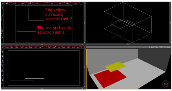
When you perform a Unite procedure with these sets in the Plan view quadrant, the results are successful because you can see that the yellow surface projects onto the red surface in this view (they overlap).
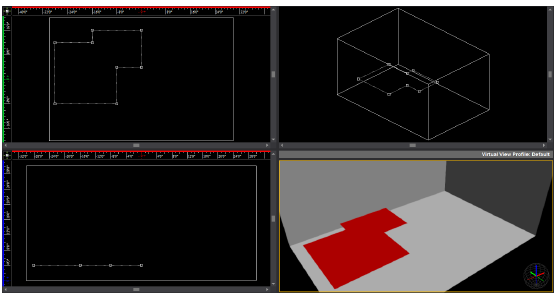
However, when you try to do the same action in the bottom left quadrant (Front View), the operation is unsuccessful because neither surface projects onto the other (they do not overlap in this view).
Tip:
To overcome this limitation, in the case noted above, you could extrude the surface in selection set 2 into a 3D solid, ensuring that the solid touches the surface in selection set 1. In some cases, it is much easier to perform a Boolean operation with 2D surfaces in the first selection set and a 3D solid in the second set because the operation is View Plane independent. For example, when you are cutting windows in walls, it is usually best to use 2D surfaces for both the windows and walls because you can project the image of the windows onto the walls (for details, see “To cut holes in walls with the Subtract tool”). However, if you have an odd-shaped building like a Pentagon, it would be impossible to align the walls with the View Plane. In this case, therefore, it would be easier to use cylinders for the shape of the windows and intersect them with the walls wherever you want a window to appear, before performing the Subtract procedure.
Examples - 2D non-parallel objects
If the surfaces in each of the selection sets are not parallel, the results of a Boolean operation can differ according to the active View Plane. In the following graphic, the red surfaces comprise selection set 1 and the yellow surface is selection set 2. Note that the yellow surface is rotated so that it is not parallel to any of the surfaces in set 1.
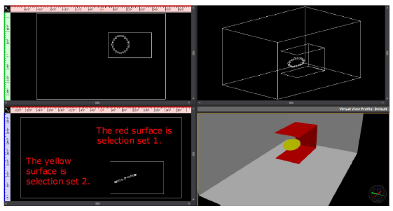
In this case, when you perform a Subtract operation in Plan view, the results are predictable: a hole the size of the yellow surface appears on the selected red surface, as shown below. Note that the hole is not perfectly circular, but rather take on the exact shape of the angled circle as it appears in Plan view.
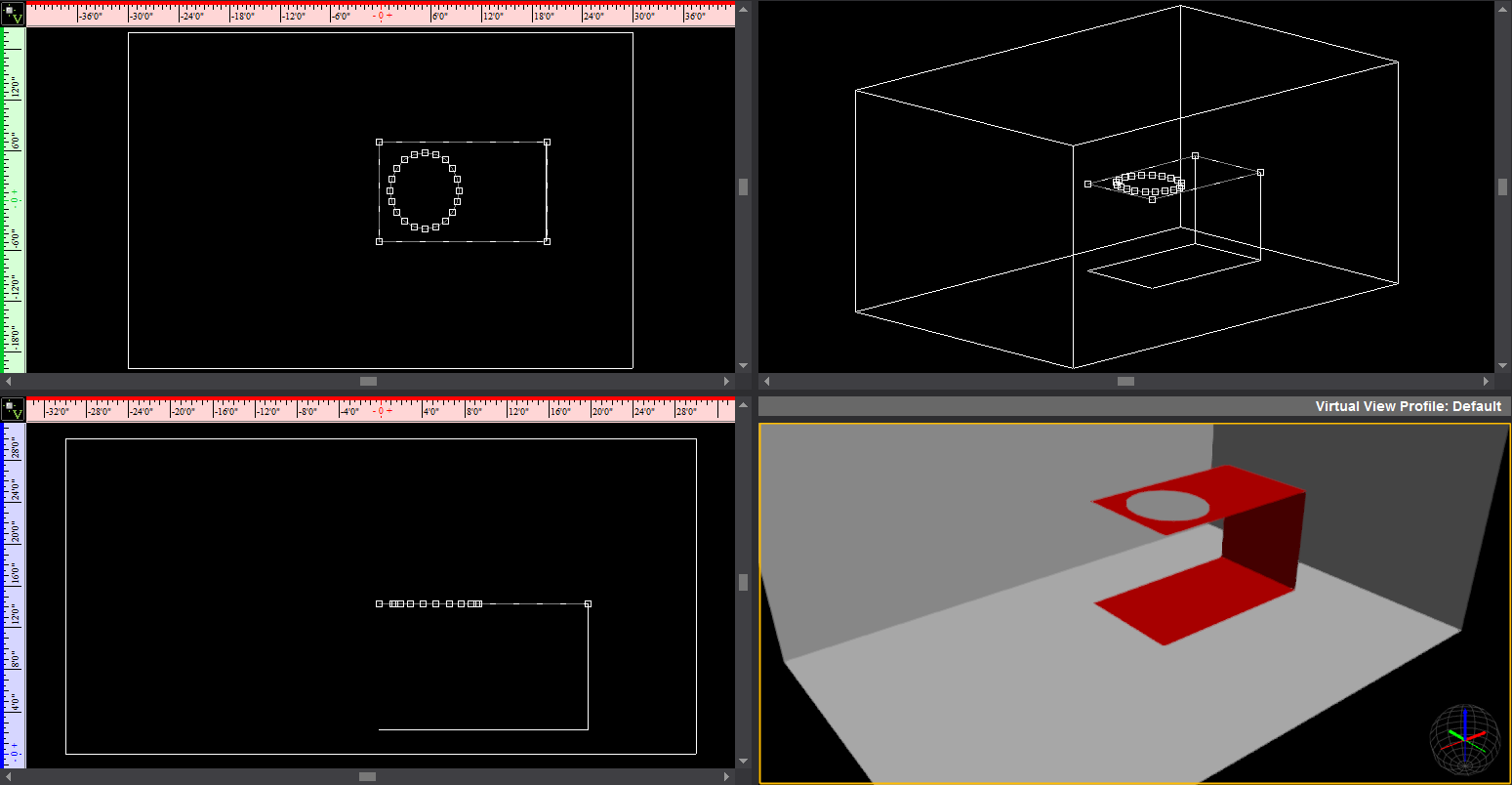
When you perform the same action in Front view, the operation fails because none of the surfaces in set 1 or set 2 is co-planar in this view.
However, when you switch to Right view and perform a Subtract, a hole appears only on the back surface (the one onto which the circle projects in this view), as shown below.
Example - 2D object and 3D solid
Note that if you convert the circular surface into a 3D solid, then you must ensure that it physically intersects with at least one of the 2D surfaces in set 1 before you can successfully perform a Boolean Operations procedure, as shown below; it is not enough for the object to project upon one of the surfaces. For details on projection and intersection, see “Projection and intersection”.
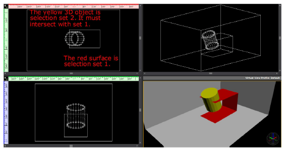
When you perform a Subtract action on these sets in Plan view, the results are as follows:
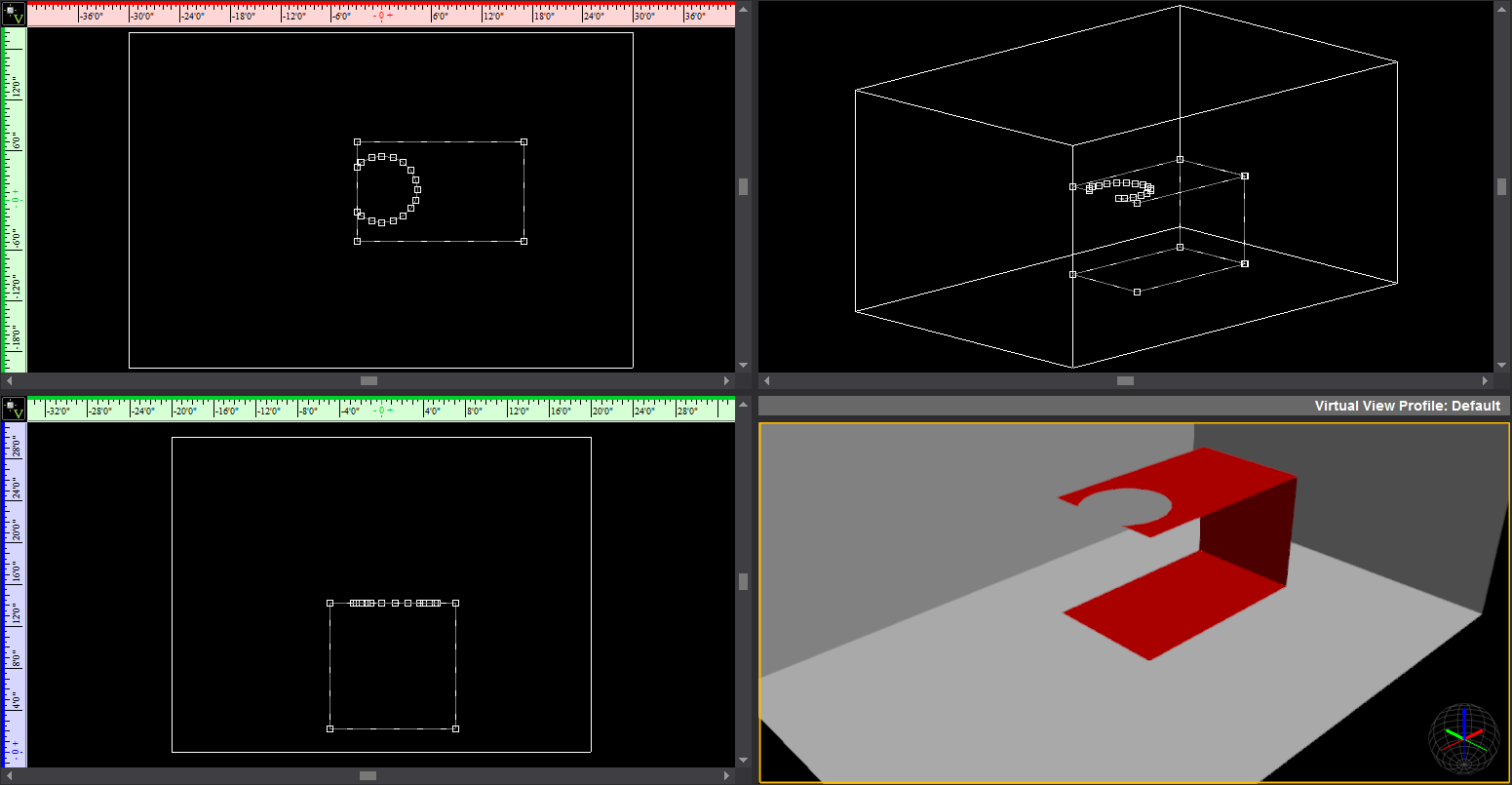
Examples of each Boolean Operations procedure
The following graphic shows the two object sets that will be used as examples in each of the procedures in this section.
Set 1 consists of the red cylinder and set 2 consists of the aqua cylinder:
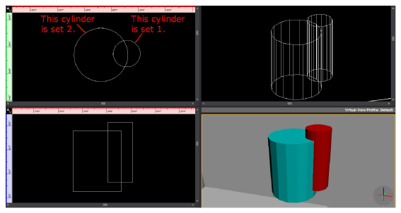
This option enables you to join two sets of intersecting objects together as one, merging their common area. Note that when you unite objects, the second set of objects adopts the properties of the first set that you chose (i.e., its color, texture, and so on).
Note: If you are uniting a 2D object like a surface with a 3D object like a riser, the 2D object must be in the first selection set and the 3D object in the second. After you perform this operation, the 3D object adopts the properties of the 2D object, becoming a flat surface with the same color and texture as the 2D object.
The following graphic shows how the two sets of objects are united to become one object. Note how the second object set (the aqua cylinder) takes on the properties of set 1, becoming red.
Note: When you perform a Boolean operation on a 3D object, the object is converted into a solid after the operation. Since you cannot apply a texture to solids, it is recommended that you convert it into a custom library object and then apply the texture. For details, see “To create a custom library item”. Alternately, you can convert the object into 2D surfaces before you perform the Boolean operation and then customize it.
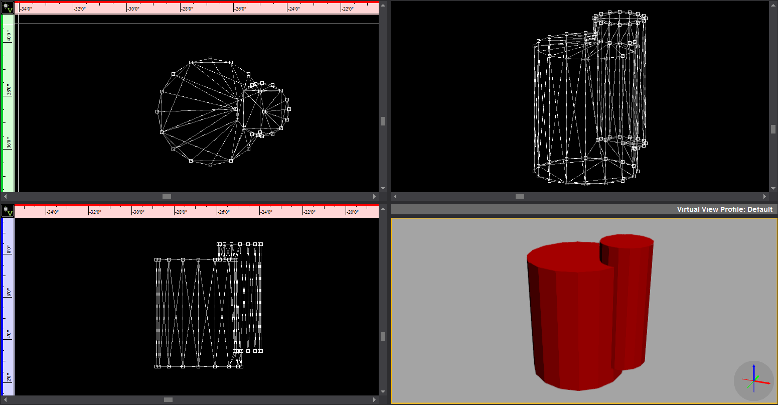
To unite objects with the Boolean Operations feature
Note that you can only select one 2D object in each selection set; you cannot select multiple 3D objects in a selection set.
1In one of the 2D wireframe views, select the first object or objects that you want to join with the second object or objects.
2Click Modify> Boolean Operations > Unite Objects.
3Click to select the second object set that you want to join with first set.
4Right-click and choose Finish Unite.
Result: Based on the complexity of your selections, you may have to wait a few moments for the calculations to finish and the objects to be united.
This option enables you to choose two sets of overlapping or intersecting objects and then delete everything outside of their common area. Note that when you intersect objects, the intersection that remains behind maintains the properties of the objects in the first selection set.
The following graphic shows the result of intersecting the red and aqua cylinders. Note how the remaining portion is red, just like the cylinder in set 1.
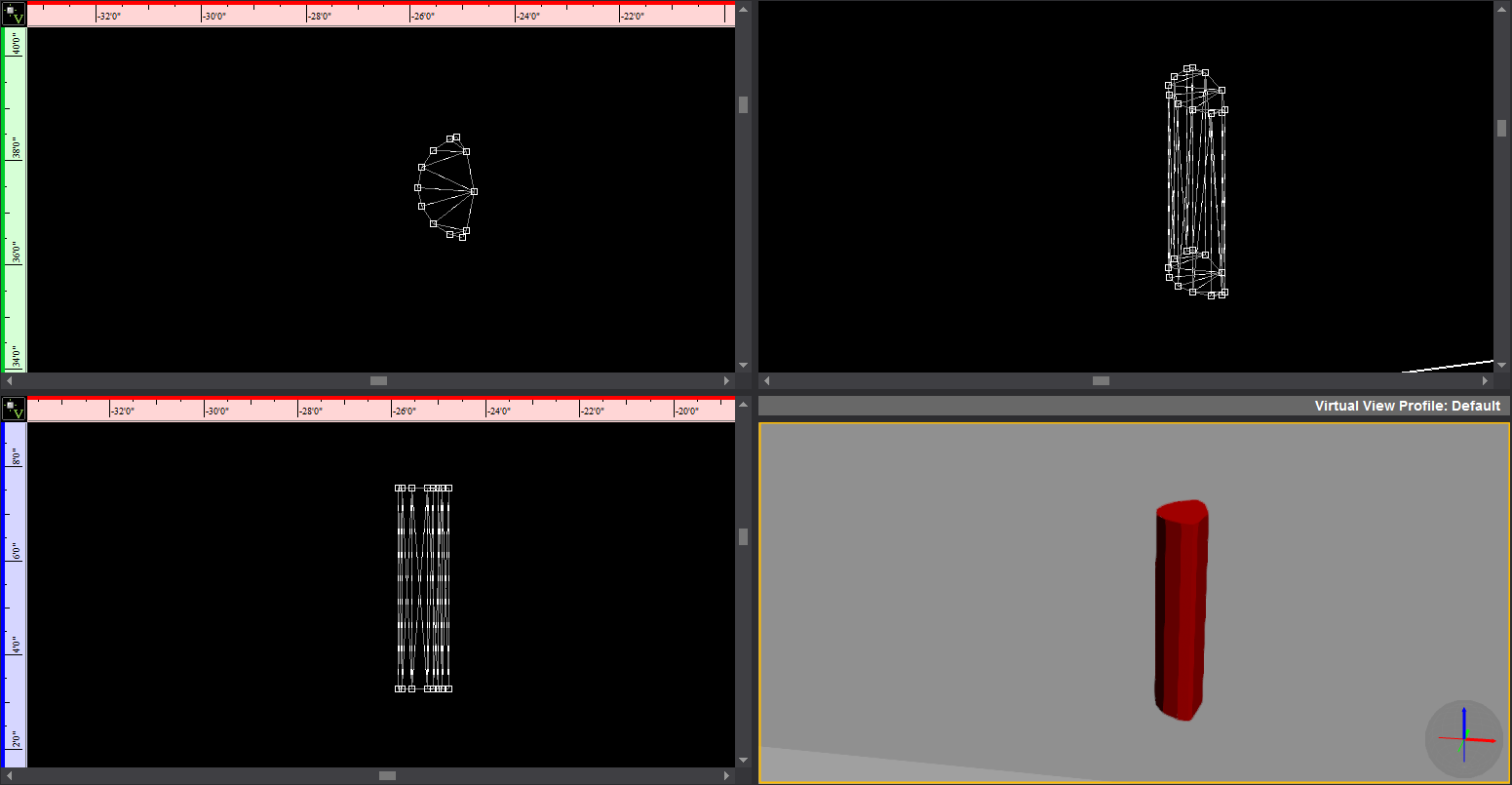
To intersect objects with the Boolean Operations feature
Note that you can only select one 2D object in each selection set; you cannot select multiple 3D objects in a selection set.
1In one of the 2D wireframe views, select the first object or objects that you want to intersect with the second object or objects.
2Click Modify > Boolean Operations > Intersect Objects.
3Click to select the second object set that you want to intersect with first set.
4Right-click and choose Finish Intersect.
Result: Based on the complexity of your selections, you may have to wait a few moments for the calculations to finish and the objects to be intersected.
This option enables you to select two sets of objects, and then subtract the overlapping area of the second set from the first set that you chose.
This feature is particularly useful for cutting a hole in a surface to create a window. Note, however, that if you are cutting a hole in a wall to create a window, it is easiest to work only with 2D objects in each selection set since they do not have to physically touch. Instead, the “window” shapes need only to project onto the walls in the active view. For details, see “Projection and intersection”. For details on cutting holes into walls, see “To cut holes in walls with the Subtract tool”.
The following graphic shows the result of subtracting the aqua cylinder from the red cylinder.
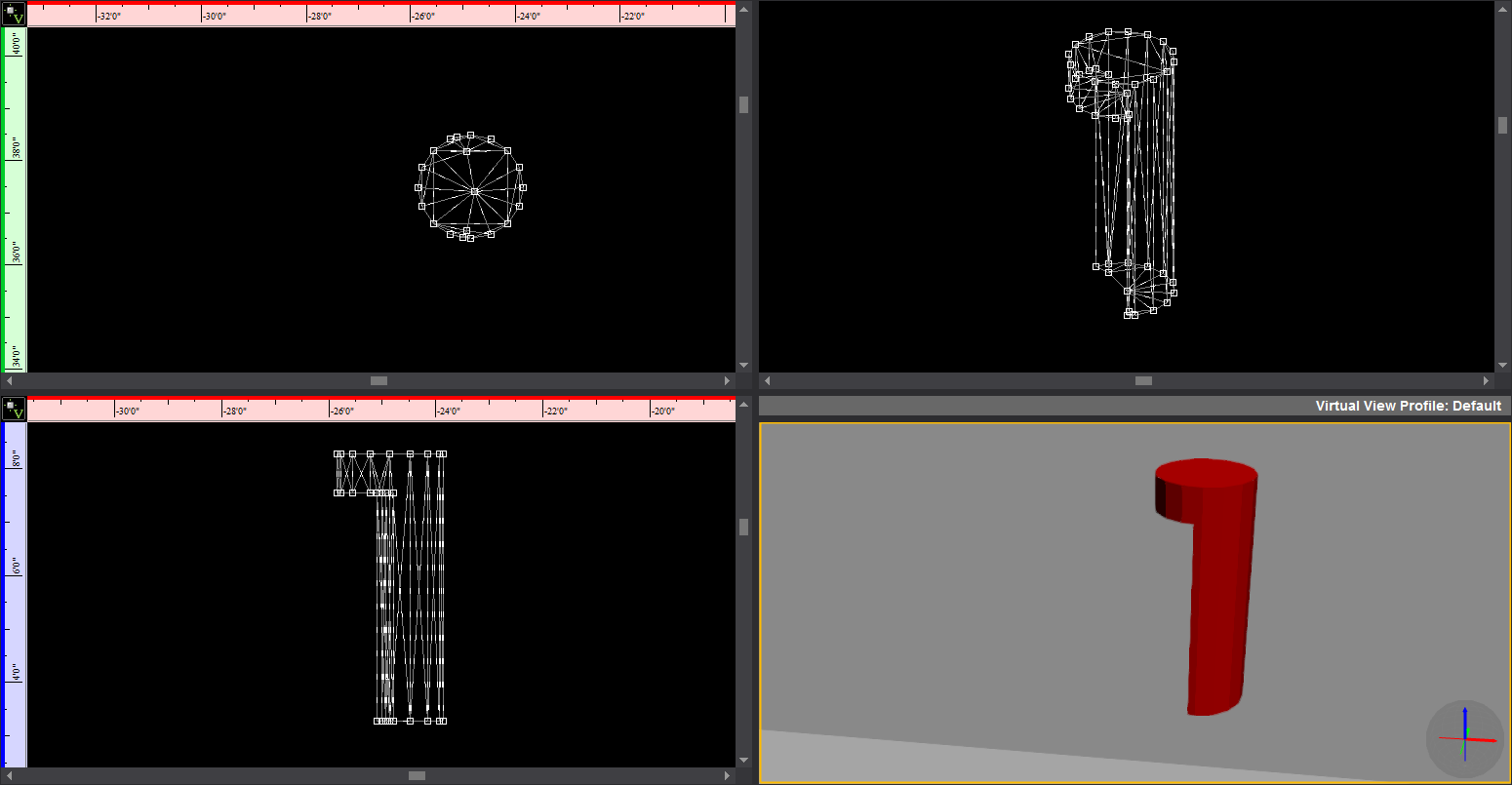
To subtract objects with the Boolean Operations feature
Note that you can only select one 2D object in each selection set; you cannot select multiple 3D objects in a selection set.
1In the Drawing Wireframe tab, select the first object that you want to keep in your drawing (the second set of objects will be subtracted from this set).
2Click Modify> Boolean Operations > Subtract Objects.
3Click to select the second object set that you want to subtract from the first set.
4Right-click and choose Finish Subtract.
Result: Based on the complexity of your selections, you may have to wait a few moments for the calculations to finish and the objects to be subtracted.
To cut holes in walls with the Subtract tool
In this procedure, you use the Boolean Operations > Subtract tool to cut a line of round windows into a wall of your venue.
1In the Drawing Quad tab, draw a venue (for example, a room).
2Click the venue to select it, and then right-click and choose Modify> Break > Solids into Surfaces.
Note: Since the window shapes are a series of 2D surfaces, it is best to convert the 3D venue into a 2D surface as well. This way, the window shapes only have to project onto the “walls” in the same plane. If the venue is a 3D object, then the windows would have to physically touch them (intersect) before you perform the Subtract operation. For details, see “Projection and intersection”.
3Click to highlight the Front view quadrant.
4Click the Circle tool, and then click OK to accept the default size of 4’.
5In the Front view quadrant, click to place the circle half-way up the wall, at one end of the room, as shown below:

6With the circle still selected, right-click and choose Modify> Convert > Circles into Surfaces.
7Type 20 and click OK. (The higher the number of points, the smoother the outline of the circle.)
8With the circle still selected, click Modify > Clone > Linear.
9In the Front view quadrant, click the extreme right-hand wall to pick the destination point.
10Type 3 for the Number in row and 20 for the Interval, and then click OK.
Result: The circular surfaces are arrayed along the length of the room.
11In the Plan view quadrant, click the wall outline to select it, and then click Modify> Boolean Operations > Subtract Objects.
12Click a circular surface, and then right-click and select Finish Subtract.
13Repeat step 11 and 12 for the next circular surface.
Result: The circular windows are “cut” into the wall of the venue, as shown in the following graphic:

This feature helps increase performance in Virtual Views by enabling you to consolidate complex objects comprising multiple polygons/”sub-objects” into objects that behave as a single entity. Consolidating meshes is essentially the same as creating new (custom) Library Items. However, while both methods make Vivien “see” the object as a single entity, when you use the Consolidate Mesh command, you don’t actually create a new Library Item, and the amount of increase in file size depends on the items that are selected.
To determine which objects in your scene to consolidate, it is recommended that you enable the new Object Bounding Box feature on the View Options tab. Once you do so, objects that appear with a high number of bounding boxes are all candidates for consolidation.
Notes:
nIt is not recommended to include library items from the WYSIWYG/Vivien library as part of the selection which mesh consolidation will be performed on.
nIf you consolidate an object to which a texture has been applied, the texture may not behave correctly because the object’s underlying geometry will be different. To maintain proper texturing AND have the file perform well for pre-visualization, it is recommended that you create a copy of the final file. Optimize the copy, and then use the optimized file for pre-programming purposes and the original file for screenshots and/or renderings.
To use the Consolidate Mesh feature
Note: Boolean Operations cannot be performed on objects that have been Consolidated.
1In a wireframe view, select the object that you want to consolidate.
2Click Modify> Consolidate Mesh.
Result: A dialog appears, asking for Mesh Consolidation to continue for all other objects and skip the Library objects.
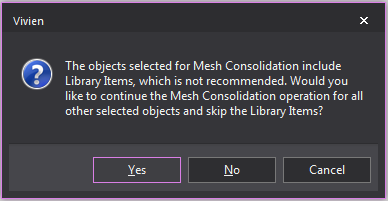
3Click Yes to proceed with the operation and excluding the Library objects.
Result: A message box appears, confirming that the operation is complete, and displaying the number of polygons that have been removed from the file.
4Click OK. The item is now consolidated into an abject that behaves as a single entity.
The Trim tool can be used to remove sections of drawn lines that intersect a referenced object (arc, circle or line) drawn on the same plane. Trimming will remove all of the selected line segment, stopping at where it intersects with the referenced object.

To trim a line
1In the drawing wireframe, select the reference object.
2From the Modify menu, choose Trim.
|
The Trim button. |
Tip: The keyboard shortcut to access the Trim tool is CTRL+T.
3Click on a segment of line you want to remove that intersects the referenced object.
Result: The selected line segment will be removed, from where the line intersects the reference object to where the line ends or intersects the object again.
4Continue trimming lines as needed.
5To end trimming line, right-click and choose Finish Trim or Abort Trim. Alternately, the ESC key can be pressed.
The Extend tool can be used to lengthen straight lines until they touch a referenced object (arc, circle or line) drawn on the same plane.
Note: Lines can only be extended if they are able to intersect the reference object when extended. If they will not intersect, the line will not extend.

To extend a line
1In the drawing, select the reference object (line, arc or circle).
2From the Modify menu, choose Extend.
|
The Extend button. |
Tip: The keyboard shortcut to access the extend tool is CTRL+SHIFT+T.
3Click on a line that you want to extend to the reference object.
Result: If the selected line can intersect the reference object, it will extend until it has done so. If the line can not intersect the object, it does not extend. The selected line will intersect all other objects in its path to reach the reference object. If the line can intersect the reference object on both ends, both line ends will extend until they intersect the reference object.
4Continue extending lines as needed.
5To end extending lines, right-click and choose Finish Extend or Abort Trim. Alternately, the ESC key can be pressed.
All objects in Vivien have properties. Properties are the characteristics or attributes that shape and define objects (for example, dimensions, color, and texture).
Properties that affect color, line weights, shading attributes, are common to all drawn objects. Objects also have properties that are particular to the type of object. When you select an object and display its properties, a tab appears in the properties dialog box for that type of object. When you select multiple objects of different types, tabs appear for each type of object selected.
To edit object properties
1Select the object(s) that you want to edit.
2From the Modify menu, choose Object Properties.
Result: The Properties dialog box opens.
Details about the options on the Properties dialog box are described in the following sections.
For information about Library object properties, see “Library object properties”.
In Vivien, there are three tabs that appear in the properties dialog box for every object in your drawing. These three tabs are the General, Appearance, and Light Emission tabs.
For 3D solids and surfaces, the Solids and Sidedness tabs also appear in the properties dialog box.
Objects also have properties that are particular to the type of object selected. A tab appears on the properties dialog box specific to that object. For details, see “Object-specific properties”.
Options on the General tab affect the selected object(s) color and line weights.

nLayer list: A list of the layers in your document displays. Click a list item to change the layer the object(s) will be drawn on.
nThe layers are listed below the Layer Groups if the Display with Layer Groups checkbox is selected.
nOnly the layers are listed if the Display with Layer Groups checkbox is clear.
nDisplay with Layer Groups: Select this checkbox to display the layers as items organized in Layer Groups. Clear this checkbox to display only the list of layers.
nCollapse All button: Click this button to display only the Layer Groups.
nExpand All button: Click this button to display the Layer Groups and all the Layers.
nUse Layer Color: Select this option to set the object(s) color for drawing views to be the same as the properties of the layer on which the object(s) resides. For more information on layer properties and the coloring objects, see “Layer properties” and “Rules for objects’ colors in Vivien”.
nClear this checkbox and use the color button to set a specific color for the object(s).
nLine Weight: From the drop-down list, choose the specific line weight for the selected object. The applied line weight is visible in all Wireframe views in all modes. For objects only, you can also choose the default setting, ByLayer, which sets the object’s line weight to be the same as the properties of the layer on which the object resides. The value Default means that the document's line weight setting from the Document Options > Object Settings window is applied to the object or layer. For more information on layer properties, refer to “Layer properties”.
nUncheck this option and enter a weight in the box below to set a specific line weight for the object(s). The line weight determines how thick the pen should be when printing a copy of the document. The applied line weight is only visible in Print Preview and when printed.
nNot available for Library items.
nHatching: Customizable styles of how the wall is viewed in wireframe view. These setting will not effect how walls are viewed in virtual views.
nShow Hatch Lines: Select this checkbox to display hatch lines on 3D solid objects and surfaces. You can click the drop-down list to select the hatch style or click the New/Edit box to create new hatch styles or edit the hatch styles. Refer to “Hatching”.
Use this tab to specify the appearance of the different components that make up the currently selected item. Based on the item that you have selected, the options in this tab differ.
You can use this tab to customize library items by adding different materials, colors, and textures to each element of the item. For example, the leaves and planter of the Potted Plant object can have different colors applied to them.
You can also use this tab to rename the individual elements of the currently selected object. This is useful for objects that contain many elements with similar names, like risers.

Note: You can apply textures to venues, surfaces, risers, walls, library items, spheres, cylinders, and cones. You can apply transparency to everything. When customizing the selected element, you can choose between applying a custom color or a custom texture—you cannot choose both. In addition to either color or texture, you can also apply material.
Highlight the element that you want to customize, and then choose one of the following options:
nColor/Texture
nIgnore Ambient Light: The selected element(s) will always appear using the color values derived from the Appearance options specified (e.g., texture). While light emission and light from fixtures will further saturate the colors displayed for the selected object, ambient light will never affect this object if this option is enabled. This option is useful when objects (except Screens) are textured with images or video, and these need to appear in their original colors at all times. In renderings, this setting is ignored if light emission is enabled.
nLayer Rendering Color: Select this option to set the object(s) color to the same as the properties of the layer on which the object resides.
nCustom Color: Select this option and then use the color button to set a specific color for the object(s).
nTexture from Library: Select this option to apply a texture from the library to the selected object(s). In the resulting window, navigate to and select the desired texture. You can apply textures to venues, surfaces, risers, walls, library items, spheres, cylinders, and cones. Click the ellipsis button (...) to change the selected texture file.
nImage Source: Select this option to apply to the selected object(s) a texture that you have created and saved in either .bmp, .jpg, .png, or .gif format. To apply the image, you must create a new Image Source. To do so, click New, and then use the Image Manager to create a new Image Source with the image you created.
nVideo Source: You can apply a video source or a subsource as a “dynamic texture” to Screen objects or Library objects with the screen element, such as projection screens, TV screens, digital display screens, etc. Select this option to apply a previously created video source or subsource, or click New to create a new video source or subsource directly from this window.
nUse Normal Map: Select this checkbox to apply an Image Source that’s a Normal Map, to create the perception of fragmented surface texture detail and depth, making objects look more realistic.
Click this drop-down box to apply an existing Normal Map image or click New to create a new Normal Map image via the Image Manager.
Note: This drop-down lists all Image Sources that appear in the Image Manager; as such, Image Sources which are Normal Maps should be named appropriately, for easy identification.
nScale: Select the height or depth of visual effect created by the Normal Map. Click the drop-down box to select the percentage scale value from not visible (0%) to maximum value stored in the imported Normal texture/image (100%).
If you have chosen a texture option, then you can also set the properties of the texture as follows:
nTile: Select this option if you want to have the texture repeated over the selected element in a continuous series of squares or rectangles, and then type the size of the frame in which you want the texture to appear in the Width and Height boxes. Based on the size that you enter, Vivien calculates how many times the texture is repeated (or tiled) to completely cover the selected element.
Note: When tiling a texture on a sphere, cylinder, or cone, by default it will completely wrap around the object. If you change the tile size, you will scale the texture up or down accordingly. If you revert back to the original tile values, you return to the default view.
nStretch: To have the texture stretch over the entire element surface, click this option button. Based on the aspect ratio and the rotation angle, Vivien evaluates the surface with all of its edges and stretches the texture so the best fit is used. Note that this option is not applicable when you apply textures to spheres, cylinders, or cones. For these objects, Tile is the only option.
nKeep Aspect Ratio: Select this option to keep the aspect ratio of the original image when it is stretched over the surface of the object you have selected. This option helps avoid distortion of complex textures. If the texture image cannot wrap completely over the entire surface of the object while maintaining its original aspect ratio, then the color that you choose in the Border Color box will be applied evenly around any excess surface area not covered by the texture (much like a picture frame around a picture).
nBorder Color: If you have chosen to preserve the texture’s aspect ratio, click this box to choose the color that will be applied evenly around any excess surface area not covered by the texture (much like a picture frame around a picture).
nNormal Map Size Multiplier: If you selected Use Normal Map, specify the number of times the Normal Map is multiplied across the object (element) to which it is applied. Type a value in the Normal Map Size Multiplier box. (Enter a valid number between 0.01 and 100.)
Notes:
nThe default value is 1 results in no changes to the Normal Map’s size; values lower than 1 will increase the size of the Normal visual effect, and values higher than 1 will decrease it.
nThe Normal Map Size Multiplier operates within the Tile or Stretch Texture Options.
nTexture / Source Tint: This option will allow the color of an object’s texture to be altered from the source color.
nTexture Rotation: If the texture has text or another recognizable image in it, you might need to rotate the image to get it right-side up. Select the rotation angle from this box.
Proceed with the following properties settings:
nMaterial Properties: Click the ellipsis button (...) to choose a material for the selected elements. Click Default to remove the selected material from the element and return to the default material.
nMaterial
When a material is selected, the properties of the material will vary from one material to the next. The Material Properties section enables these default material settings to be changed. Each property value can be changed on a scale from 0%-100%. An explanation of the value is found on the right side of the property.
nTransparency: This setting controls the proportion of light that passes through the material. 0% being completely opaque, 100% being completely clear.
nSpecular Level: This setting controls how prominent other specular effects appear on the material. 0% being no visibility of specular effects, 100% being a maximum visibility of specular effects.
nSpecular Gloss: This setting controls the level of gloss a material will project. 0% will project the gloss over a wide area, 100% will concentrate the gloss in a small area.
nSpecular Color Source: This setting controls the color of light projected on a material. 0% will show only the color of the light, 100% will show only the color of the material.
nLight Reflection: This setting controls the amount of light that is reflected off the material. 0% having no reflection, 100% being specular.
nDisplay Reflection in Virtual Views: This setting controls whether true reflections are shown by the object’s material in Virtual Views.
You can use this procedure to rename object elements that have similar names, giving them a more descriptive name. For example, if you have customized a riser, you could give each side of the riser a distinct name according to its custom properties. This is especially useful for custom objects that you have drawn and are going to save as custom library items. Since you cannot rename individual elements of custom library items, it is best to do so before you save the item.
1Under Elements, highlight the element that you want to rename. For example, highlight Riser - Back.
2Click Rename.
3Type the new, descriptive name for the element.
4Click OK.
5Click OK in the Appearance tab to save your changes.
Cast Shadow
The Cast Shadow feature gives you the option to cast shadows and display footprints of objects in Virtual View.
nCast Shadow: Select this checkbox to display in Virtual View, the footprint/shadow of the selected object. By default, Cast Shadow is enabled for all objects; on the other hand, Cast Shadow is disabled for all hang structures and fixtures by default.
Options on the Light Emission tab affect the light emission properties for the selected object(s). Light emission is defined as the ability for objects to glow or emit light and can be used to simulate LEDs, lasers, neon, light boxes, projection screens, glowing furniture, and so on.

Highlight the element that you want to customize, and then choose one of the following options:
nLight Emission Glow
In this section, you can enable or disable the Light Emission Glow feature per object or per Element of an object.
Note: Glow must be enabled in the Light Emission section of the Visual Effects tab in the View Options window to show the light emission glow effect from objects in Virtual View.
nEnable: Select this checkbox to display in Virtual View the light emission glow effect from the selected Element of the selected object.
Clear this checkbox to disable the light emission glow effect from the selected object.
By default, Light Emission Glow is enabled for all objects except Screens.
Tip: Screen objects have a separate glow option, called Screen Glow, which is enabled globally via the View Options > Simulation tab in Virtual View.
Note: If Light Emission Glow is enabled for a selected Element of an object with multiple Elements (such as Risers, Cylinders, etc.), only the selected Element will show the light emission glow effect in Virtual View.
nEnable Light Emission: Select this checkbox to enable light emission for the object, and then choose the light emitting properties.
nColor: Click the color box to choose the color of the light emission. Note that this color overrides the object's original color, so it is best to choose a similar, if not identical, color.
nIntensity: Select the light-emitting intensity of the selected object. To adjust the brightness of the object as it appears in renderings and Virtual Views, choose a new intensity from this drop-down list.
Options on the Sidedness tab affect how the selected object appears in Virtual Views and renderings. Aside from the tents that come with the Vivien library, you cannot change the sidedness of any of the objects that come with Vivien, either library objects or default venues. By default, all objects in the Vivien library except the tents are double-sided, which means that when you rotate them in Virtual Views, all sides display equally and you cannot see through them. Conversely, the default venues that come with Vivien are single sided, which enables you to see “into” the venue when you rotate the image in Virtual Views. (By default, the tents in the library are also single-sided, which means you can see through them in the Virtual View. However, you can change this feature by making the tent double-sided. For details, see “To change an object’s sidedness”.)
You can also change the sidedness of objects that you have drawn in another program and imported into Vivien (i.e.,.dwg, .dxf files or SketchUp files) or objects that you have drawn in Vivien, such as custom venues, surfaces, or custom objects that you have added to the library.
For these objects, you can use this tab to change the sidedness from single to double sided, or vice versa. For example, if you have drawn a venue as double sided, you can select it and change it to single sided so that it behaves in the same manner as the default Vivien venues (i.e., you can see into the venue as you rotate it in Virtual Views). If you prefer to have an outside view of the custom venue, then the double sided option is best as it prevents you from seeing “through” the walls.
Note: You can also use this feature to flip the faces of a custom surface from one direction to the other if you do not like the way the object appears in the Virtual View. For example, if the color or texture of the imported object is facing inward when viewed on the Virtual View tab, click to select the object on either of the drawing tabs. Right-click and choose Object Properties. Click the Sidedness tab. Click Flip Normal, and then click OK.
To change an object’s sidedness
You can use this procedure to change objects from single to double sided and vice versa. You can also flip the faces of a single-sided object so that they are oriented in the opposite direction, either inward or outward.
Note: Aside from the tents that come with the Vivien library, you cannot change the sidedness of any of the objects that come with Vivien, either library objects or default venues. By default, all other objects in the Vivien library are double-sided, which means that when you rotate them in Virtual Views, all sides display equally (they are not see through). Conversely, the default venues that come with Vivien are single sided, which allows you to see “into” the venue when you rotate them in Virtual Views.
1Select the object that you want to edit.
2Right-click on the object, and then select Object Properties.
Tip: At any time, to access an object’s properties, you can click the Object Properties tool on the Modify toolbar.
Result: The Properties dialog is displayed.
3Click the Sidedness tab.
4Click the appropriate option button, either Double Sided or Single Sided. To leave the single-sided object’s faces oriented in the same direction in which they were drawn, proceed directly to step 6. To change the direction of the faces, see step 5.
5If you are changing a double-sided object to single sided, and you want to change the direction in which the object’s faces are oriented (either outward or inward), select the Flip Normal checkbox.
6Click OK.
7Review your changes in the Virtual View tab and make adjustments as required.

nDouble Sided: Select this option to turn the single-sided object into a double-sided object. Note that aside from the tents in the Vivien library, you cannot change Vivien’s default venues from single to double sided.
nSingle Sided: Select this option to turn the double-sided object into a single-sided object. For example, if you have created a custom surface/wall/venue and have imported it as a double-sided object into Vivien, you can select it and make it single sided so you can see “into” the venue when you rotate it in Virtual Views.
Note: Aside from the tents in the Vivien library, you cannot change any of Vivien’s other library objects from double to single sided.
nFlip Normal: If you have imported a custom-drawn object or drawn an object in Vivien and you see in the Virtual View that it appears incorrectly (the “faces” showing the texture/color are pointing inward), select this checkbox to flip the faces in the opposite direction, and then look at the object in the Virtual View again.
Objects also have properties that are particular to that type of object. For example, light fixtures have unit numbers, but do not have a radius. When you select an object and display its properties, a tab appears in the Properties dialog box for that type of object. When you select multiple objects of different types, tabs appear for each type of object selected. The following objects are defined here:
npoints
nlines
ncones
nspheres
ntext labels
ndimensions
nlibrary items
nlight fixtures
nprojectors
For venues, refer to “Defining the venue”. For circles, arcs, walls, risers, cylinders, spheres, screens and cameras, refer to “Drawing objects”. In these cases the properties dialog offers the same options that were given when the object was initially drawn.
The Colors window allows for full customization and control over colors used in Vivien. From here the color of any object in Vivien can be changed. This section will explain the various features of the color window.

nStandard: A hexagon of basic colors and shades available for selection.
nOK: Will confirm the use of a new color to replace the current color.
nCancel: Will exit the color window without making a color selection.
nSelect...: This option is used to gather a custom color sample from anywhere on your desktop. This option will turn the cursor into a dropper from which colors can be gathered.
nNew: Color selected in the Color window.
nCurrent: The color that is currently in use.
nSaved Custom Colors: A saved palette of custom colors.
nAdd to Custom: Will save selected New color to the Saved Custom Colors palette.
nCustom: Section for editing a selected color’s properties.

Options on the Point tab affect how the selected points are drawn. The default point type used in a document is defined on the Object Settings tab of Document Options. To ignore the default setting, clear Use Document Defaults and select the desired point type.

Options on the Line tab affect how the selected lines are drawn.

nLine Pattern: Choose a line pattern for the selected line(s). “Drawing lines” for an illustration of each type.
Note: Line patterns are available for a Rectangle, Circle, Ellipse, Arc, and Elliptical Arc, in the corresponding Properties window.
nScale: Type a value in the Scale box to change the length and spacing of dots and dashes for the selected line(s). This is applicable to center, hidden, or dot lines only.
nClosed: Check this option to connect the first point of a multi-segment line to the last point of that line.
nSpline: Check this option to transform a line into a spline or french curve.
Note: You cannot change a line to a spline or french curve unless the selected line has more than two vertices.
nArrow Options: How arrows attached to the line will be shown.
nDisplay: Select this checkbox to show an arrow at the end(s) of the line.
nLocation: Where the arrow will appear on the line.
nArrow Size: How large the arrow will appear.
nArrow Offset: How far away the arrow if from the line.
nArrow Type: The style of arrow that will be displayed.
nDouble Line: Select this checkbox to display the line as a double line.
nDistance: How far apart the double lines will be from each other.
nVirtual View Options: Check the Shade option to have the selected lines displayed in Virtual Views and renderings. Type a value for the radius to set its weight.
Options on the Cone tab affect how the object is drawn.

nHeight: Type a value to change the height of the cone.
nHorizontal Radius: Type a value to change the width of the base surface.
nVertical Radius: Type a value to change the depth of the base surface.
nLock Ratio: Select this checkbox to lock the shape proportion when the size of the cone is changed.
nSmooth Shading: Select this checkbox to display a smooth appearance in Virtual View.
nNumber of Segments: Type a value to change the number of vertical divisions that appear when the cone is broken into surfaces, or lines, or set pieces.
nNumber of Stacks: Type a value to change the number of horizontal divisions that appear when the cone is broken into surfaces, or lines, or set pieces.
nUse Document Defaults: Clear this checkbox if you want to specify the Number of Segments and the Number of Stacks.
Options on the Sphere tab affect how the object is drawn.

nHorizontal Radius: Type a value to change the width of the middle of the sphere or equator.
nDepth Radius: Type a value to change the horizontal depth of the middle of the sphere or equator.
nVertical Radius: Type a value to change the vertical depth of the middle of the sphere or equator.
nLock Ratio: Select this checkbox to lock the shape proportion when the size of the sphere is changed.
nSmooth Shading: Select this checkbox to display a smooth appearance in Virtual View.
nNumber of Segments: Type a value to change the number of vertical divisions that appear when the sphere is broken into surfaces or set pieces.
nNumber of Stacks: Type a value to change the number of horizontal divisions that appear when the sphere is broken into surfaces or set pieces.
nUse Document Defaults: Clear this checkbox if you want to specify the Number of Segments and the Number of Stacks.
Options on the Text Label tab affect the justification and style of the selected text labels.

nText Label: Type new text to change the label.
nUse SHIFT+ENTER to type on the next line.
nUse ENTER to close the dialog (equivalent to the OK button).
Tip: You can also type text labels with information listed in the Event Info table using smart variables %Variable Name% in Text Label. The information will be displayed automatically. For example, use %Director% and the name of the Director stored in the table will appear in the Text Label.
nInsert Smart Variable: Open the Smart Variables window and select a smart variable text from the table of smart variables that are listed in the Event Info tab in Document Options.
nMultiline Text Alignment: How the text in the Text field will be aligned.
nHeight: Section for controlling the height of the text label.
nSpecify for: Choose how you would like to specify the height of the Text Label.
nIndividual Line of Text: Sets the height for a single line of text.
nAll Lines of Text: Sets the total height of all lines of text.
Example: If you set this to 4' and there are 4 lines of text, then each line of text will be 1' in height.
nText Label Padding: Adds space between the text and the text label border.
nTotal Text Label Height: The height of the text and text label padding combined.
nFont: Section for controlling the font settings of the text label.
nUse Document Defaults: Clear this checkbox to choose the default font and font styles for all text labels, and then make your selections.
nAnchor Position: Section for controlling how the text label is anchored.
nHorizontal: Select the Text label’s horizontal alignment from the drop-down menu. The available horizontal alignment options are:
nLeft: Places the selected text label to the left of the insertion point.
nCenter: Horizontally centers the selected text label on the insertion point.
nRight: Places the selected text label to the right of the insertion point.
n Vertical: Select the text label’s vertical alignment from the drop-down menu. The available vertical alignment options are:
nTop: Places the selected text label below the insertion point.
nCenter: Vertically centers the selected text label on the insertion point.
nBottom: Places the selected text label above the insertion point.
nCallout and Arrow: Section for controlling how callout lines and arrows attached to the line will be shown.
nShow Callout: Select this checkbox to display the text label with a callout line.
nPattern: The pattern of the callout line.
nScale: The dimension at which the callout pattern is to be viewed at making it legible.
nCallout Position: The position on the text label where the callout will extend.
nShow Arrow: Select this checkbox to show an arrow at the end of the callout.
nStyle: The style of the callout arrow that will be displayed.
nSize: How large of the callout arrow that will appear.
nUse Label Color: When selected will use the same color as the text label for the callout. If not selected a different color can be chosen.
nLock Callout Position: When selected will lock the position of the callout when the text label is moved.
nAlign to View: Select this checkbox to set the text labels to be legible regardless of plot type.
Options on the Dimension tab affect the appearance and measurement mode of the selected dimension(s). To change the length of a dimension, it must be stretched in the drawing.

nLinear Dimension: View and change how the linear dimension is displayed.
nLength: This box is not editable. It displays the actual length of the line drawn for the dimension.
nDisplayed Length: Select the checkbox and type a value you wish to display.
nView Type: This box is not editable. It displays the plot type in which the dimension label is visible, which is determined when the dimension is drawn.
nOrthographic Mode: Select the view in which the dimension will be visible.
nRotate: Select the checkbox to rotate the linear dimension.
nAngle: Type the angle of rotation.
nFill: Select the checkbox and click the color select box to change the fill color behind the dimension text.
nOptions: Customize the other elements of the linear dimension.
nUse Document Defaults: Toggle this option to specify whether the dimension is to use default document settings as configured in the Dimension tab, or use custom settings.
nText Height: The height of the text used in the dimension.
nText Offset: The positive or negative offset of the text.
nShow Leader Line: Select this checkbox to display the leader line that connects the text to the linear dimension.
nExtension: The length of the extension lines.
nOffset: The distance from extension line from the object being measured.
nArrow Size: The size of the arrow head used on the dimension.
nArrow Type: The style of arrow head used on the dimension.
nMeasurement Units: Measurement modes are explained in “Drawing dimensions”. Select Imperial or Metric to change the measurement units.
nDisplay Units: The preferred way to display measurements. For Imperial measurements, choose between Feet & Inches, or just Inches; For Metric, the options are Meters, Centimeters or Millimeters.
nPrecision: Specify the measurement precision of the dimension line. Based on your choice for measurement units, you can choose to display the drawing resolution in centimeters, millimeters, whole numbers, or fractions.
nDisplay Alternate Unit: Select this checkbox to display the alternate unit.
nAlign To View: The orientation of the text used in the dimension. Select the checkbox to set the horizontal alignment of the text to match your view.
Once a wall is created its properties can be edited in the Wall tab. This is accessible by selecting the wall and selecting Modify > Object Properties > Wall.

nWidth: Current width of the wall.
nHeight: Current height of the wall.
nThickness: Current thickness of the wall.
nTransparency: A measure of how solid the wall appears to be. 0% being opaque, 100% being transparent.
nBack Transparency: Transparency setting for the back of the wall.
nFront Transparency: Transparency setting for the front of the wall.
To view library object properties
1Open the Library Browser.
2Navigate to the desired object.
3Select the object and then click the Properties tool at the top of the Library Browser.
|
The Properties button. |
or
Hold the ALT key and double-click the object name.
Result: The Properties dialog box for the selected object opens.
Two tabs appear in the properties dialog box for every object in the library: Appearance and Characteristics. Light fixtures also have Options and Projection tabs.
Tips:
nYou can open properties dialog boxes for multiple objects at one time. You might want to do this to compare data, such as weight information.
nTo view library object properties without opening individual property boxes, browse the library using the shortcut bar. To do this, select the shortcut bar for the type of object you want to view. Right-click in the shortcut bar and choose New Object (for example, New Chair). The Library Selection dialog box opens with a properties pane included.
nYou can modify some object properties create the look you want. You can also associate costing information with each object. For details, “Customizing object properties”.
The Appearance tab displays a Virtual View and an image of the symbol for the library item.
nView Type: Indicates whether the Virtual View of the object is fixed (static) or animated (moving).
nView: Click Plan, Side, or Front to view the object symbol in the different views. The Wireframe view changes depending on the view type that you select.

Options on the Event Resources Defaults tab are read-only and are set when the object is added to the library.

nVersion: Release number of the library object.
nStatus: Status of the library object. Beta indicates that the object is completed but not verified. Release indicates that it has been tested and is accurate. A status of Preliminary indicates that the object has minimal functionality.
nAuthor: The individual or company that constructed the library object.
nSupplier: The company or individual that provides the library object
nWebsite: The relevant website of the library object.
nCost: The cost of the library object.
nExt. Price: The extended price, or markup placed on the library object.
nNotes: Any notes that pertain to the library object. The notes usually pertain to the simulation capabilities in Vivien.
nEdit Defaults: A menu for editing the selected library item’s Supplier, Website, Cost and Ext. Price characteristics.
For more information on how to manage the properties of event resources, “Managing/Editing resource properties”.
After you use the Projection Wizard to draw a projector on its own or a projector/screen combination, you can use the Properties dialog to change the settings of the projector and screen. If you double-click a projector/screen combination, the following tabs appear:
nDrape Kit (only if you have drawn a folding screen)
nScreen Frame
While most of the boxes on the Properties tabs are the same as those that appear while you create the projector/screen, a couple of boxes are unique to these tabs, meaning that you can specify certain types of properties only through the Properties tabs, as shown in the procedures that follow.
To hide the projection rays in wireframe view
By default, when you draw a projector, the projection rays are shown in Wireframe views. However, you can use the Projector properties tab to hide them.
1In the Drawing Wireframe or Drawing Quad tab, click to select the projector, and then right-click and select Object Properties.
2Click the Projector tab.
3Click to clear the checkbox beside Show Projection Rays in Wireframe.
4Click OK.
To specify the diameter of the screen’s support frame/tripod
By default, when you draw a projector and screen (or a screen on its own), the diameter of the supporting frame is set to one inch. However, you can change the diameter to any value you like, as shown below.
1In the Drawing Wireframe or Drawing Quad tab, click to select the projector/screen (or just the screen), and then right-click and select Object Properties.
2Click the Screen Frame tab.
3In the Support Diameter box, type the new diameter of the screen’s support frame or tripod.
4Click OK.
The Image Manager enables you to store images as sources in Vivien, and then change the properties of saved sources instead of working with individual images. For example, by using the Image Wizard to assign textures to saved sources instead of to specific images, you can change or modify the texture of multiple objects at the same time.
The Image Manager also enables you to perform minor image modifications, such as flip horizontal or flip vertical to images without permanently changing the source file. This feature is useful in situations where the texture is flipped as a result of incorrect surface winding. For details, see “Drawing surfaces”.

Notes:
nThe Image Manager window preview can be resized to accommodate images that have a higher or wider aspect then the default window size.
nThe Image Manager window preview will display a grey checker pattern to identify the alpha levels that are defined in an image.
nThe maximum resolution of an image that can be imported into the Image Manager is equivalent to 4,194,304 pixels (2048 x 2048). You can import into the Image Manager, images that are very wide and not tall, or vice versa.
To access the image manager
1Select Managers> Image Manager.
Result: The Image Manager appears.

To create a new image source in the image manager
1In the Image Manager, click New.
2Browse to locate the image on your computer, and then click OK.
Result: The image is added as a source.

Notes:
nSource Name: The image’s file name.
nSource Path: The path to the physical file. Click the file open icon to select a new file.
nFlip Horizontal: Click this option to flip the image source horizontally. For details, see “To flip an image source”. Note that you cannot flip image subsources.
nFlip Vertical: Click this option to flip the image source vertically. For details, see “To flip an image source”. Note that you cannot flip image subsources.
nDimensions: The file’s dimensions in pixels.
nIn Use: Informs you of whether the image source is in use. If the image source is currently in use, it cannot be deleted from the Image Manager.
nDisplay Settings
nShow image at: Select the zoom level for the image. You can choose to "fit" the image in the display window, or show it at a percentage of its actual size: 100%, 200% or 300%.
nDisplay Borders: Select this option to show the subsource borders in the display.
nDisplay Selected Only: When you have selected a subsource in the table, select this checkbox to only show the subsource in the display area; if you do not select this checkbox when a subsource is selected, the entire source is shown (with the subsource borders highlighted in the display if you selected Display Borders).
In situations where a surface was drawn in a clockwise direction (see “Drawing surfaces”), the texture may appear to be “flipped” either horizontally or vertically. To avoid this problem, flip the image source using the Flip Horizontal or Flip Vertical checkboxes, as shown below. Note that you cannot flip image subsources; only the actual image source can be flipped.
1Open the Image Manager.
2In the table to the left, select the image source that you want to flip.
3Based on the direction in which you want to flip the image, select either Flip Horizontal or Flip Vertical.
Result: The image is flipped, as shown in the following sample graphic, which was flipped vertically.

To export an image source
After flipping the image, you may want to save your changes to a new image file as follows:
1Open the Image Manager.
2In the table to the left, select the image source that you want to export.
3Click the Save icon in the top left of the window.
4Type a name and select a file type for the new image, or accept the default file type of PNG.
Note: When exporting an image source the default file type is PNG, but you can choose a different file type, if desired; when exporting a subsource, you cannot choose the file type. The subsource is exported to the same file type as its source.
5Click OK.
When you move image files from their original location, they may not load from within Vivien. When this happens, the image source will be highlighted in red, as shown in the following graphic:

To address this issue, select the image source highlighted in red, click the folder icon beside the Source Path box, and browse to select a new image. When you are finished, click OK.
Just as with videos, you can create one subsource or multiple subsources from an image using the following procedures. Image subsources are useful in scenarios where you need to apply part of an image to one object and another. Normally, to do so you would need to open the image in a photo editing software program, make your edits, crop the image, and then import two images. However, with the image subsource creation feature, you can just import the source file, and create the necessary subsources within Vivien. For example, you could use this procedure if you have a photo that you want to break into quadrants (2 x 2), and then apply each quadrant to a separate surface, screen or LED wall, etc.
To create a single image subsource
1In the left pane of the Image Manager, click to highlight the image which you want to create a subsource for.
2In the bottom left corner of the window, click Single Subsource - create one.

3Type the subsource name.
4By default, the system uses the start and end coordinates of the selected source, but you can change these values as desired. When you change these values, the system automatically updates the dimensions.
5Click the Border box to specify the color of the border that will appear around the subsource when displayed.
6Click OK.
To create multiple image subsources
1In the left pane of the Image Manager, click to highlight the image you want to create subsources for.
2In the bottom left corner of the window, click Multiple Subsources - create many.

3Type the subsource name.
4Define the subsource matrix by specifying the number of columns and rows. The dimensions of the subsources are displayed for your reference.
5By default, the subsources are created by taking the overall source area (height & width) and evenly dividing it by matrix provided. However, you can modify the total area by changing the start/end coordinates and, therefore, the overall dimensions used to create the subsources. To do so, click the checkbox beside Modify total area for subsources, and then type the new coordinates.

Notes:
nSubsources are always listed below the source from which they were created.
nThe table in the Image Manager provides a convenient way of displaying source/subsource information; all sources and their subsources are grouped, and can be expanded/collapsed.
nYou can rearrange the columns in the table by clicking the column header and dragging it to the new position.
nYou can adjust the width of columns by clicking the column border and dragging the column to its new width.
To clone an existing subsource to a new image
1In the left pane of the Image Manager, click to highlight the image you want to clone a subsource to.
2In the bottom left corner of the window, click Clone From Existing Subsources.

3Select the media type that contains the subsource you want to clone, either Image Sources or Video Sources.
4Select the desired subsource from the corresponding source drop-down menu.
5Enter a name for the cloned subsource in the Subsource Prefix field.
6Click Apply.
Result: The selected subsource will be cloned and applied to the selected image.

Changing the properties of image sources
Note: If you change the source after the subsources were created, and the new source has different dimensions that do not match the subsources dimensions, the affected subsources are highlighted in yellow (and a dialog appears to notify you as such).
When you select a row in the Image Manager table, the properties of the image source are displayed in the Source Properties area of the window. You can change various properties of the image source as follows:
nTo change the border color of image subsources, in the table, click the appropriate border color and then click on the drop-down box that appears to select the new color. Click Update.
nTo change the name of the image source or subsource, in the table, click the appropriate row. Type the new name, and then click Update.
nIf you have already applied an image to multiple objects, and then you want to replace the source file with something different, you can make the change once in the Image Manager and have it automatically applied to all related objects (i.e., you don’t have to individually apply the changes to each object's properties). To do so, you change the underlying source file to the Image name.
nYou can define a subsource either by its start/end coordinates or by its dimensions:
nTo resize the subsource, click the appropriate row in the table. Change the start/end coordinates as desired, and then click Update. Note that if you change the coordinates, the system updates the dimensions automatically.
nTo change the dimensions of a subsource, click the appropriate row and then type the new dimensions. Note that when you change the dimensions, the system will automatically add to the start coordinate to determine a new end coordinate. Click Update.
The Video Manager enables you to bring a live or pre-recorded video into Vivien and play it back. To do so, you create video sources, which you can then assign to screens and to projectors that you have inserted in your file from the Library Browser. For details on drawing screens, see “Drawing screens”.
Notes:
nTo play the video, you use the Video Tool. For more information, see “Using the Video Tool”. You can view the video in any of the Virtual Views, using the controls on the Video Tool to pause, fast forward, rewind, or stop the video.
nBefore you render your drawing, you can either pause the video at the precise image you want to see in the final rendering, or you can let the video run while the Render Wizard processes the information in your drawing. In this case, the Render Wizard captures the video frame that was showing when it processed the screen information.
nThe Video Manager window can be resized to accommodate videos that have a higher or wider aspect then the default window size.

To access the video manager
Select Managers> Video Manager.
Result: The Video Manager appears.

nVideo File is a pre-recorded video saved in your computer in a specified video file format. Vivien supports video files in the following formats:
nMPEG-4 “.mp4”
nMPEG-2 “.mpg”
nMatroska “.mkv”
nWindows Media Video “.wmv”
nAudio Video Interleave (AVI) “.avi”
nQuickTime File Format (QTFF) “.mov”
Note: If you cannot view these file types, you may not have the proper CODEC installed on your PC. Install the appropriate CODEC, and then try viewing the file again. For more information about playing back video files and the use of CODECs, please see https://forums.cast-soft.com/index.php?threads/playing-video-files-in-vivien.1172/.
nVideo Capture is a live video stream that comes from an external video capture device or a Blackmagic Design Device.
nCamera (I-Mag) is a Video Source that displays the view from Cameras drawn in Vivien when applied to the Screens, Video Projectors, and LED Walls.
Video subsources
Video Sources can be split into subsources in the Video Manager. This enables you to apply portions of the video to multiple screens, 3D primitives, LED Walls, or projectors. For more information on creating Video subsources, see “Splitting video into subsources”.
To create a new video source in the video manager
1In the Video Manager, click the New icon.
Result: The Video Source window appears.

2In the Name box, type the name of the Video Source.
3Select the Video Source from the options in the Input section.
n Video File: Click Browse to select the video file you wish to use. For more information about video file playback, please see http://forums.cast-soft.com/index.php?threads/playing-video-files-in-wysiwyg.370/.
n Video Capture: Select to use live video stream captured from an external device that is attached to your computer.
Note: When a Blackmagic Design video capture device is detected, the Video Capture with Blackmagic Design Device radio button is automatically selected. In order for these devices to work properly, always use this option, not the Video Capture option above it. To connect them, their input source and resolution are selected through the utility that was installed with their driver.
n Camera (I-Mag): The view from the camera drawn in Vivien.
4Browse to locate the video on your computer, and then click OK.
Result: The video is added as a source.

nName: The video’s file name.
nSource: The path to the physical file.
nDimensions: The file’s dimensions in pixels.
nIn Use: Informs you of whether the video source is in use. If the video source is currently in use, it cannot be deleted from the Video Manager.
nMute: Indicates if the sound has been muted in the video.
nDisplay Settings
nShow video at: Select the zoom level for the video. You can choose to Fit the video in the display window, or show it at a percentage of its actual size: 100%, 200% or 300%.
nPlaceholder: Select this options to display the placeholder that was set in the Source Properties section.
nBorders: Select this option to show the subsource borders in the display.
nSelected Only: When you have selected a subsource in the table, select this checkbox to only show the subsource in the display area; if you do not select this checkbox when a subsource is selected, the entire source is shown (with the subsource borders highlighted in the display if you selected Borders).
nSource Properties
nSource Name: The video file’s name.
nPlaceholder: Select the image file that was created in Image Manager, or click New to create a new placeholder image in Image Manager.
nFlip Horizontal: Select this option to flip the video source.
nFlip Vertical: Select this option to flip the video source vertically.
n4-byte Alignment: Select this option to align the pixels of a distorted video image. The 4-byte Alignment checkbox is automatically available only if the video source requires the alignment.
For details on using the Video Designer Tool to play the video, see “Using the Video Tool”.
After you setup the video source in the Video Manager, you can take the video source and split it up into subsources that you can apply to multiple screens, 3D primitives, or projector-style fixtures that you have inserted from the Video Projection section of the Fixtures library.
To do so, click the Split Video tab in the Video Manager, select a video source that you set up, and then split it either manually (by defining the pixel coordinates of each split) or automatically/evenly (by setting the number of rows and columns). You can then split these subsources further, if desired.
Once you split the video into subsources, you can attach the subsources to the objects that you want to use to display the video, just as you would attach a regular video source, and then play the video using the Video Designer tool.
To create a single video subsource
1In the left pane of the Video Manager, click to highlight the image for which you want to create a subsource.
2In the bottom left corner of the window, click Single Subsource - create one.

3Type the subsource name.
4By default, the system uses the start and end coordinateds of the selected source, but you can change these values as desired. When you change these values, the system automatically updates the dimensions:
a.Start Coordinate: Type the starting coordinate for the subsource (the top-left corner of the subsource) in the format “x,y”, where x is the horizontal coordinate and y is the vertical coordinate. Note that the coordinate system uses the top-left corner as the origin (0,0). also note that when video is shown at 100-300%, a tooltip appears under the cursor, indicating its position.
b.End Coordinate: Type the ending coordinate for the subsource (the bottom-right corner of the subsource) in the format “x,y”, where x is the horizontal coordinate and y is the vertical coordinate. Note that the coordinate system uses the top-left corner as the origin (0,0).
5Click the Border box to specify the color of the border that will appear around the subsource when displayed.
6Click OK.
To create multiple video subsources
1In the left pane of the Video Manager, click to highlight the video for which you want to create subsources.
2In the bottom left corner of the window, click Multiple subsources - create many.

3Type the subsource name.
4Define the subsource matrix by specifying the number of columns and rows. The dimensions of the subsources are displayed for your reference:
a.Number of columns: Type the number of columns of subsources to be generated. If the video resolution cannot be equally divided by this number, the remaining pixels will be left at the end (for the horizontal pixels this means the ones at the far right, and for the vertical pixels this means that ones at the bottom.).
b.Number of rows: Type the number of rows of subsources to be generated. If the video resolution cannot be equally divided by this number, there will be a few gaps in the generated subsource grid.
5By default, the subsources are created by taking the overall source area (height & width and evenly dividing it by matrix provided. However, you an modify the total area by changing the start/end coordinates and, therefore, the overall dimensions used to create the subsources. to do so, select the checkbox beside Modify total area for subsources, and then enter the appropriate values:
a.Start Coordinate: Type the starting coordinate for the subsource (the top-left corner of the subsource) in the format “x,y”, where x is the horizontal coordinate and y is the vertical coordinate. Note that the coordinate system uses the top-left corner as the origin (0,0). also note that when video is shown at 100-300%, a tooltip appears under the cursor, indicating its position.
b.End Coordinate: Type the ending coordinate for the subsource (the bottom-right corner of the subsource) in the format “x,y”, where x is the horizontal coordinate and y is the vertical coordinate. Note that the coordinate system uses the top-left corner as the origin (0,0).
6Click OK.
Result: The following graphic shows a video with nine subsources (three columns and three rows).

Notes:
nSubsources are always listed below the source from which they were created.
nThe table in the Video Manager provides a convenient way of displaying source/subsource information; all sources and their subsources are grouped, and can be expanded/collapsed.
nYou can rearrange the columns in the table by clicking the column header and dragging it to the new position.
nYou can adjust the width of columns by clicking the column border and dragging the column to its new width.
To clone an existing subsource to a new video
1In the left pane of the Video Manager, click to highlight the video you want to clone a subsource to.
2In the bottom left corner of the window, click Clone From Existing Subsources.

3Select the media type that contains the subsource you want to clone, either Image Sources or Video Sources.
4Select the desired subsource from the corresponding source drop-down menu.
5Enter a name for the cloned subsource in the Subsource Prefix field.
6Click Apply.
Result: The selected subsource will be cloned and applied to the 60 selected video.

Changing the properties of video sources and subsources
Note: If you change the source after the subsources were created, and the new source has different dimensions that do not match the subsources dimensions, the affected subsources are highlighted in yellow (and a dialog appears to notify you as such).
When you select a row in the Video Manager table, the properties of the video source or subsource are displayed in the Source Properties area of the window. You can change various properties of the video source and subsources as follows:
nTo change the border color of video subsources, in the table, click the appropriate border color and then click on the drop-down box that appears to select the new color. Click Update.
nTo change the name of the video source or subsource, in the table, click the appropriate row. Type the new name, and then click Update.
nIf you have already applied a video to multiple objects, and then you want to replace the source file with something different, you can make the change once in the Video Manager and have it automatically applied to all related objects (i.e., you don’t have to individually apply the changes to each object's properties). To do so, you change the underlying source file to the Video name.
nYou can define a subsource either by its start/end coordinates or by its dimensions:
nTo resize the subsource, click the appropriate row in the table. Change the start/end coordinates as desired, and then click Update. Note that if you change the coordinates, the system updates the dimensions automatically.
nTo change the dimensions of a subsource, click the appropriate row and then type the new dimensions. Note that when you change the dimensions, the system will automatically add to the start coordinate to determine a new end coordinate. Click Update.
Note: You can use the Video Tool to apply the Video Subsources. For details, “Using the Video Tool”.
To configure a new video source for streaming video
To create a new video source for streaming video, you use the Video Manager. There are a couple of ways of opening the Video Manager (for example, from the New Screen window, or from the Tools menu); the following procedure lists one possible way.
1Click Managers > Video Manager.
2Click the New icon in the upper-left corner.
Result: The Video Source window opens.
3In the Name box, type a descriptive name for the video.
nTo play a video from a file, click the Video File option button, and then click Browse to locate the file.
nTo capture a live video stream from an external source, such as a web cam or a video capture device that is attached to your computer, click Video Capture, and then use the drop-down arrow to select the appropriate device. Vivien will detect what standard resolutions the capture device can support, and display them in the Resolution drop-down box; click this drop-down to choose your preferred resolution.
If you select a Video Capture option, configure the Input and Resolution values for the device:
nInput: Choose between various inputs found on video capture devices (e.g., HDMI, DVI, S-Video, and so on).
nResolution: Select the resolution of the incoming video, provided that multiple resolutions are available from the selected input.
Note: The Video Capture option must not be used when a Blackmagic Design video capture device is used; when using such devices, you must click the next option, Video Capture with Blackmagic Design Device. Devices from manufacturers can only be detected and used if their driver is of the WDM (Windows Driver Model) type. In order for Vivien to be able to connect to the video capture device, that device must not be currently in use by another application.
nA Blackmagic Design Device is automatically detected in Vivien. The Video Capture with Blackmagic Design Device radio button is automatically selected if a Blackmagic Design Device is detected. A text prompt appears below the Video Capture radio button confirming the detection and asking to select the Blackmagic Design Device. Use the drop-down box to select the Blackmagic Design Device.
Note: As with all other capture devices, in order for Vivien to connect to Blackmagic Design devices, that device must not be currently in use by another application.
nTo play a view of a drawn Camera, click Camera (I-Mag) and select the Camera from the drop-down.
4To mute the sound of the video, in the Video Manager table, select the checkbox in the Mute column. If this checkbox is not selected, the video’s sound will play.
5Click OK. If the video is available, it connects automatically.
6Click OK to save your changes and close the Video Manager.
Vivien includes textures that simulate various types of surfaces, such as brick or cloth. You can apply textures to different objects, such as surfaces (created with the Surface tool or by extruding a line), drape lines, library objects, and venues. You can also use your own bitmap or jpeg files as textures, to simulate projection screens, or to cover a surface with a texture specific to your event.
Vivien supports Alpha Mapping with PNG images. Camera view can look through and lighting beams can pass through transparent sections of these images.
Alpha Level supports Alpha Blending for Camera on overlapping surfaces with transparency. Two overlapping translucent surfaces will be displayed accurately showing the levels of intersecting transparencies.
When customizing an object, you can apply either a color or a texture; you cannot apply both.
Note: You can apply textures in Vivien only if you have installed them; in most cases, they are automatically installed with the Vivien software.
To apply a texture to a surface
The following procedure details how to apply a texture to a surface, but it can also be used to apply a texture to other objects by right-clicking, and then selecting Object Properties.
1Right-click on the surface to which you want to apply a texture, and then choose Object Properties.
2Click the Appearance tab.

3Select the texture option that you want. The options are:
nTexture from Library: Indicates that the selected surface is a texture from the Vivien library. The texture name appears in the box provided. Click the ellipsis button (...) to modify the selected surface.
nImage Source: The selected surface uses a texture from an external bitmap or jpeg file on your hard drive rather than one from the Vivien library. Click the ellipsis button (...) to select the external file to be used as a texture.
nVideo Source: This option is only available for objects with the screen element such as projection screens, TV screens, etc. The selected screen element applies the texture from a live or pre-recorded video source. Click on the drop-down menu to select from the images stored and available in Video Manager, or click New to create a new video source in the Video Manager.
nUse Normal Map: The selected surface uses an Image Source that’s a Normal Map, to create the perception of fragmented surface texture detail and depth, making objects look more realistic.
Click the drop-down box to apply an existing Normal Map image or click New to create a new Normal Map image via the Image Manager.
Note: This drop-down lists all Image Sources that appear in the Image Manager; as such Image Sources which are Normal Maps should be named appropriately, for easy identification.
Click the Scale drop-down box to set the height or depth of visual effect created by the Normal Map. Click the drop-down box to select the percentage scale value from not visible (0%) to maximum value stored in the imported Normal texture/image (100%).
4Select Tile to have the texture repeated over the selected element in a continuous series of squares or rectangles, and then type the size of the frame in which you want the texture to appear in the Width and Height boxes. Based on the size that you enter, Vivien calculates how many times the texture is repeated (or tiled) to completely cover the selected element.
OR
Select Stretch to make the selected texture grow to cover the entire surface. Based on the aspect ratio and the rotation angle, Vivien evaluates the surface with all of its edges and stretches the texture so the best fit is used. This option is not active unless you choose a texture.
Tip: To preserve the aspect ratio of the texture so it is not distorted when stretched over the surface, click Keep Aspect Ratio.
5To choose a custom border color for the texture when it is stretched over the surface, click the Border Color box, and then choose the custom color.
6If you selected Use Normal Map, you can specify the number of times the Normal Map is multiplied across an object (element) to which it is applied. Type the value in the Normal Map Size Multiplier box. (Enter a valid number between 0.01 and 100.)
Note:
nThe default value of 1 results in no changes to the Normal Map’s size; values lower than 1 will increase the size of the Normal visual effect, and values higher than 1 will decrease it.
nThe Normal Map Size Multiplier operates within the Tile or Stretch Texture Options.
7If the texture has text or another recognizable image in it, you might need to rotate the image to get it right-side up. Type the rotation angle in the Rotation (Deg.) box.
8Click OK.
Vivien supports simple Alpha Mapping with PNG images. Camera view can look through and lighting beams can pass through transparent sections of these images that were set as textures.
Alpha Level supports Alpha Blending for Camera on overlapping surfaces with transparency. Two surfaces with transparency levels that overlap will be displayed accurately showing their transparencies crossing each other
When Alpha Beam Shadows is enabled, alpha fill percentage/value in images are utilized when altering the beam’s color and intensity as it passes through surfaces with transparency. See “Simulation tab” in Virtual View options.
Beams do not handle different levels of Alpha fill. Beams will only pass through the images with Alpha fill level between 0 and 127 of 255.
In a PNG image file:
nAreas of the image filled with any level of transparency will work correctly as transparent or semi-transparent textures in Virtual View.
nAreas of the image filled with higher transparency (Alpha fill level between 0 and 127 of 255) will allow beams to pass through.
nAreas of the image filled with lower transparency (Alpha fill level between 128 and 255) will not allow beams to pass through.

Notes:
nEach alpha shadow level supported for this feature requires additional video memory from your graphics card, which can impact performance depending on your scene and computer hardware.
n Alpha texturing is supported with PNG images containing alpha transparency build into the image. For more information about using Alpha Textures, please see http://forums.cast-soft.com/index.php?threads/using-alpha-in-r38.662/.
nThe Image Manager window preview will display a grey checker pattern to identify the alpha levels that are defined in the image.

Normal Map images may be applied to objects to make them appear three-dimensional without actually modifying their geometry; the perceived visual effect is that of a fragmented surface with high and low points that correctly interact with light.

Materials differ from textures in that they do not affect what the objects or surfaces look like, but rather how they interact with light. The result of applying a material is only apparent in renderings, as shown below.

Objects and surfaces can be assigned both a texture and a material.
You apply materials using the Appearance tab in the Object Properties dialog box. Vivien provides an assortment of materials from which you can choose.

To apply a material to an object
1Right-click the object to which you want to apply the material, and then choose Object Properties.
Result: The Properties window will appear.
2In the Properties window, click the Appearance tab.

3From the Elements list box, choose the elements to which you want to apply the material. To choose a custom material for the selected elements (such as metal, paper, plastic, or fabric) click the ellipsis button (...) beside the Material box.
Result: The Material Select window will appear.
Tip: When a material is highlighted in the Material Select window, a preview of the material applied to objects is displayed.

4In the Material Select window, navigate to and highlight the desired material, and then click Select.
Result: The settings of the element will be configured so that it simulates the material.
5If desired, you can edit the default properties of the selected element. The element options vary as follows:
nTransparency: This setting controls the proportion of light that passes through the material.
nSpecular Level: This setting controls how prominent other specular effects appear on the material.
nSpecular Gloss: This settings controls the level of gloss a material will project.
nSpecular Color Source: This setting controls the color of light projected on a material.
nLight Reflection: This setting controls the amount of light that is reflected off the material.
Notes:
nUse the drop-down menus to change any of the material properties. Use the Reset button to revert back to defaults.
nThe beam will pass through a surface with the Transparency value set to 80% or greater. The beam will not pass through the surface when the value is lower than 80%.
6Click Apply.
7Click OK.
The reflective properties of a material can be toggled to enable true reflections in Virtual Views. When enabled, the material will produce a detailed and faithful representation of everything reflected on its surface.
Attention: The number of reflective material surfaces that Vivien can support is 10. When enabling reflections on an object, note the number of surfaces that make up the object. For example, a cube has 6 sides. If an entire cube was to be reflective, it would use 6 reflective surfaces.

To apply reflections to an object (surface object or venue)
Note: The quality of reflection is based on the material properties of the object. Dull or unreflective materials will reflect poorly.
1Right-click the object to which you want to apply the material, and then choose Object Properties.
Result: The Properties window will appear.
2In the Properties window, click the Appearance tab.
3From the Elements list box, choose the elements of the object which you want to apply the reflection.
Note: Remember Vivien limits the number of reflective surfaces to 10.
4In the Material Properties section, select the checkbox by Display Reflection in Virtual Views.
5Click Apply.
6Click OK.
7Go to Virtual View.
8Go to Options > View Options....
Result: the View Options window will open.
9In the View Options window, click the Simulation tab.
10Under the Materials section, select the Enable checkbox.
11Select the checkbox by Reflections.
12Click OK.
Result: Reflective materials will be enabled and demonstrate true reflections in Virtual View.
Applying a material to a Library object element
You can apply different materials to each element of Library objects using the Appearance tab in the Properties dialog box.
To apply a material to a Library object element
1Right-click the library object to which you want to apply material, and then choose Object Properties.
2Click the Appearance tab.

3From the Elements list, select an element.
4If a material was chosen previously, it is listed in the Material Properties box. To choose a different material, or to choose a material for the first time, click the ellipsis (...) button, and then navigate to the new material.
Note: Click Default to remove your selection and apply the default material to the element.
5Repeat steps 4 and 5 for each element to which you want to apply materials.
6When finished, click OK.
You can apply the same texture and material settings to multiple objects using the Quick Texture Tool.
To use the Quick Texture Tool
1From the Tools menu, click Quick Texture.

nTo apply a texture, click Apply Texture, and then select one of the following options: Use Layer Rendering Color, Use Custom Color, Use Texture from Library, or Use Texture from File. Complete the remaining texture options as desired.
nTo apply a material, click Apply Material, and then select the material type by clicking the ellipsis button (…). Specify the transparency to use default or custom values.
2Click OK.
Result: The Quick Texture Settings window closes and the Vivien workspace reappears. The cursor changes to a circle with a Q symbol attached, indicating that you are in Quick Tools mode.
3Using your mouse, click on the object to which you want to apply the texture/material settings.
Result: The Quick Texture Tool’s element selection window appears.

4From the list on the left, select the elements to which you want to apply the texture/material settings.
5Optionally, with the elements selected, make any last-minute changes required to your texture/material settings.
6Click OK.
Result: The texture/material settings are applied to the object.
7Repeat steps 4 to 6 for as many objects as desired.
8When you are finished, right-click and select Finish Quick Tools.
Vivien includes the following drawing tools:
These are described in the next sections.
By default, the origin is set at the center point of the Vivien venue defined for the event. (For more information on venues, see “Defining the venue”.) You can reset the origin to another point in your drawing so that a different point assumes the values (0,0,0).

1From the Tools menu, choose Set User Origin.
or
Click the Origin tool on the Tools toolbar.
|
The Origin button. |
2Click a point on your drawing or type in the coordinates (X, Y, Z) for the point that assumes the values 0,0,0.
Note: When you start typing, the Command Line prompt automatically appears at the bottom of the window.
To reset the user origin
From the Tools menu, choose Restore Document Origin.
Result: This resets the origin back to the Vivien default origin.
You can draw objects using a dialog box to set the object’s size (width, depth and height for example). Once you set the object dimensions, the full-size object is then attached to the cursor so you can place it in the drawing.
Alternately, you can draw objects in freehand mode by clicking the Freehand button in the object dialog box. Freehand Mode allows you to click an insertion point for the object first, then drag to create the extents of the object as allowed by the view (XY for plan view, XZ for front view, and so on).
For risers and cylinders, once you have set the dimensions, a dialog box opens to allow you to set the third dimension, if required. Freehand Mode works with Walls, Risers, Cylinders, Circles, Arcs, and Spheres.
To set Freehand Mode as the default drawing mode
1From the Options menu, choose Document Options.
2Click the User tab.
3In the Options section, check Freehand object creation.
4Click OK.
To set Freehand Mode on the fly
From the Tools menu, choose Freehand Mode.
or
Click the Freehand Mode tool on the Tools toolbar.
|
The Freehand Mode button. |
Remember to click the Freehand Mode
tool again to leave Freehand mode.
The coordinate not represented in the 2-dimensional Plan view of your drawing is called Height and is assigned the axis letter z. In Plan view, you cannot move an object in your drawing in the direction of the Height value (i.e., up and down from floor to ceiling); you can only move objects along the x and y axes. In Plan view, the status bar identifies the Height value as z=[value].
Notes:
nIn the other 2D views (side views and front/back), the direction in which you cannot move objects is assigned different axis letters, based on the view. For example, in a side view, you can move objects from floor to ceiling (z axis) and from left to right (y axis) in the room, but you cannot move objects into the center of the room (along the x axis). Notice in these views that when you move your mouse, the coordinate value for this axis on the status bar does not change.
nFor 3D perspective views you are still limited to working in two dimensions. To work in a 3D view, you set the workplane (the 2-dimensional plane that you want to work in).
When you place objects on drawings in the Plan view, by default they are placed on the floor (z=0). To place objects on a surface higher than the floor (for example, a stage), you could first place them on the floor, switch to a view where z is not the Height value (for example, the Front view) and manually drag the object up.
A simpler technique is to change the Height value in Plan view, in effect shifting the floor up. When you change the Height value for the Plan view from z=0 to some other value, for example z=4, all objects placed in that view are placed 4 feet above the ground (or 4 meters if you are using the Metric system). Although you cannot see the difference in the Plan view, you can see it when you switch to Left, Right, Front, Back and 3D views of the room. The Height value affects all subsequent objects inserted in the Plan view; it does not affect objects that are inserted in any other view type.
Note: The Height value is not a move tool. Objects are not moved to the Height value. The Height value only affects subsequent inserts.
To enter a value for the Height
1From the Tools menu, choose Height.
or
Click the Height tool on the Tools toolbar.
|
The Height button. |
Result: The Enter the Height dialog box opens.
2Type the value in the Height box, and then click OK.
Snaps are used to assist in the drawing and placement of objects. When a snap setting is active, the cursor is drawn to the applicable snap point, like a magnet. You can have multiple snaps active at the same time.
To toggle snapping on and off
From the Tools menu, choose Snap Mode and then Snap State.
Result: A check mark displays beside Snap State when snapping is on. No check mark displays when snapping is off.
Note: You can turn snapping on at any time by selecting a snap type from the Tools toolbar.
To select a snap type
1From the Tools menu, choose Snap Mode and then one of the snap types described next.
or
Click a snap type on the Tools toolbar.
2Repeat step 1 until
all desired snap types are selected.
Aligns the placement of objects to grid points. You can set the grid interval and angle in the Draw Options page of the View Options dialog box.
Aligns the placement of objects to the end-point of another line.
Aligns the placement of objects to the mid-point of another line.
Aligns the placement of objects to a point in the drawing.
Light fixture insertion points are considered as points. Therefore, you can align the placement of objects to light fixtures (snap to light fixtures), using the Point snap.
Aligns the placement of objects to the intersection of lines, circles or arcs on the same plane.
Aligns the placement of objects to the centerpoint of lines, circles or arcs on the same plane.
To snap to the center of a circle, arc, or elliptical arc, hover around that center point in the space of the circle, arc, or elliptical arc.
Library snap displays snap points at the bounding box corners of the library item which aligns the placement of the object in the drawing. The insertion point is identified as the single snap point in a corner that is displayed in red if the object is not selected, which will turn to green if the object is selected. Refer to “Using library snap”for more details.
Insertion points are pre-defined snap points on a 2D/3D primitive object or Library object that are used as insertion grips when placing objects into your drawing.
This feature allows you to choose the Insertion Point from a list of pre-defined Insertion Points. Drawn objects or Library objects use a default insertion point. When you choose a different Insertion Point, the object will shift around the cursor, to the specified Insertion Point. The object will automatically use the same Insertion Point that was previously selected until changed.
Insertion Points for Library objects will only display if Library Snap is enabled. See “Using library snap” for more details.
To select the object’s insertion point
1Choose a 2D or 3D object to draw, or select an object from the Library.
2Set or change the object’s specifications in the settings dialog box that appears.
3Click OK.
Result: Your cursor snaps to the default insertion point of the object.
4Right-click the object to display the menu list of insertion points.
5Click on the new insertion point.
6Place the object into your drawing.
To select the Library object’s insertion point
See “Specifying library item insertion point”.
You can change the insertion point of a single 2D/3D primitive object in your drawing to another insertion point. You can select only one 2D/3D primitive object to change its insertion point. You can change the insertion points of rectangles, arcs, elliptical arcs, polygons, risers, cylinders, cones, spheres, walls, and screens.
To change the object’s insertion point
1Select a 2D or 3D object in your drawing.
2From the Edit menu, choose Change Insertion Point, and click on the new insertion point from the menu list of insertion points.
Tip: You can right-click on the selected object, choose Change Insertion Point, and click on the new insertion point from the menu list of insertion points.
Result: The insertion point of the selected object moves to the new location.
Orthographic Mode is used to constrain your mouse movement and drawing to a direction parallel to a specified axis. This is useful for placing objects in alignment.
When Orthographic Mode is inactive, you can draw or move objects in any direction on the workplane.
The view type determines the possible axes of movement; XY for plan views, YZ for side views, XZ for front and back views.
To activate orthographic mode
From the Tools menu, choose Orthographic Mode and then Orthographic State.
or
You can activate Orthographic Mode at any time by clicking the Ortho tools on the Tools toolbar.
To select an axis of movement
From the Tools menu, choose Orthographic Mode and then an axis of allowed movement.
or
Click an Ortho tool on the Tools toolbar.
![]() : X-Axis
: X-Axis
Allows movement in the X-direction.
![]() : Y-Axis
: Y-Axis
Allows movement in the Y-direction.
![]() : Z-Axis
: Z-Axis
To cancel and reset ortho buttons
1From your keyboard, use F8 to disable any ortho buttons that you have chosen.
2Use F8 again to reset the same ortho selection as that which was previously selected.
From your keyboard, you can use ALT + F8 to enable Ortho mode for only one axis of the current view or workplane.
nPress ALT + F8 for the first time to enable the first Ortho axis of the current view or workplane regardless of the current Ortho state (i.e. both axes on or both axes off).
nPress ALT + F8 for the second time to disable the first Ortho axis and enable the second Ortho axis.
nFrom a single axis Ortho mode, press F8 once to disable the Ortho mode.
nFrom a single axis Ortho mode, press F8 twice in sequence to enable double axes Ortho mode.
Use the Tape Measure tool to measure the distance and angle from one point to another.
To measure a distance
1From the Tools menu, choose Tape Measure.
or
Click the Tape Measure tool on the Tools toolbar.
|
The Tape Measure button. |
2Click the starting point for the measurement.
3Click the end point of the measurement.
Result: The length and angle of the specified trajectory displays in the status bar.
Tip: When selecting the starting and end points for the measurement use the snap tools for precision. For details about the snap tools, see “Snaps”.
The angle tool enables you to measure and display the angle between two intersecting lines.
To measure an angle
1From the Tools menu, choose Angle.
2Pick the starting point of the measurement.
3Pick the end point of the measurement.
Result: The angle between the two intersecting lines is displayed on the cursor’s information tooltip and in the bottom left corner of the Status bar.
The Position Tool helps you determine the position of your selected object or objects in the Drawing Wireframe, providing the precise coordinate reference numbers for the X, Y and Z axes.
The Position Tool can be used to change the position of your selected object or objects by specifying new coordinate numbers for the X, Y and Z axes.
To use the Position Tool
1Select an object in drawing wireframe view.
2Click the Position Tool tab.
Result: The Position Tool window appears showing the selected object’s reference coordinate numbers in the X, Y and Z scroll boxes.
3Click the X, Y or Z scroll box arrows to increase or decrease the reference coordinate numbers.
OR
On the Position Tool window, you may click the X, Y and Z boxes and type the numbers.
Result: The position of the selected object(s) changes according to the new coordinate reference numbers.
Notes:
nYou can select more than one object and you can move more than one object.
nIf multiple objects are selected and arrow buttons are used, the objects move to relative positions.
nIf multiple objects are selected and a coordinate value for an axis is entered, the objects move to the same position. For example, if multiple objects are selected and you entered a coordinate value in the Z axis box, the objects move to the same Z axis coordinate.
nThe increment/decrement size is equal to the Grid Interval property in Document Options > Draw Defaults tab.
Position tool shortcuts
You can open the Position Tool using the following shortcuts:
nCTRL + ALT + P: Opens the Position Tool window.
nCTRL + SHIFT + X: With an object selected, opens the Position Tool window and the cursor in X.
nCTRL + SHIFT + Y: With an object selected, opens the Position Tool window and the cursor in Y.
nCTRL + SHIFT + Z: With an object selected, opens the Position Tool window and the cursor in Z.
The command line is an area in Vivien where you can enter coordinates for the purpose of placing or editing objects in a document. You can often place objects more quickly and with more precision using the command line.
Generally, coordinates are specified X, Y, Z. You can, however, insert coordinates using either two or three values. When using two values, the third value is assumed from the Height. For more information on the Height, “The Height value”.
The values that you specify when the units are set to imperial are assumed to be in feet unless otherwise specified. Similarly, the values that you specify when the units are set to metric are assumed to be in metres unless otherwise specified. You can at any time specify values in both imperial and metric measurements (for example, 5”, 3cm, 6’).
The following example illustrates the many different methods to use the command line.
Example
1In a plan view, from the Draw menu, choose Line.
2Type 0,0 as the starting point of the line.
Result: When you start typing, the Command Line toolbar opens.

3Press ENTER to establish the first point of the line at the origin.
4To set the next point at exactly X=5 and Y=5, type 5,5, and then press ENTER.
Result: A new line segment displays and it assumes Z from the Height.
5To place the next point of the line 10 units to the right and 5 units up (in Y) from the last point, type @10,5 and press ENTER.
Result: A new line segment displays.
6To place the next point at exactly 5 feet, 3 metres, and 6 inches from the last point, type 5’, 3m, 6”, and then press ENTER.
Result: A new line segment displays.
7When you are finished drawing the lines, right-click and select Finish Line.
Layers are drawing aids that help you organize your drawing. One way to think of layers is as transparent acetate sheets upon which you can draw. In the same way that you can view several transparent sheets at once by placing them on top of each other, you can hide and show layers by choosing which sheets are in the stack. The top sheet is the layer that new objects are placed on and is called the current layer. You can also merge layers together if you decide that you need to combine one or more layers.
Note: Layers can be extremely useful drawing aids, and are recommended for every file that you work on. For example, you could create the following layers to organize every file:
n"Venue" (which is created automatically when a Venue is drawn)
n"Tables and Chairs"
n"Misc Furniture" (such as Podiums, bars, food tables, etc.)
n"Stage"
n"Lighting"
n"People"
To find out the layer to which any object in your plot is assigned, just hover over the object with your cursor in any of the wireframe views. A tooltip appears listing the object name and its layer. This is especially useful when you are working with multiple layers, some of which have the same color.
Layers can be organized into Layer Groups in the Layer Database window. The Layer Groups feature is enabled or disabled from the Document Options window. Layer Groups can be created, viewed, modified and deleted in the Layer Database window. Refer to “Layer groups”.
1From the Managers menu, choose Layers.
Result: The Layer Database window is displayed.
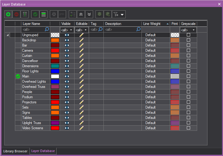
2To create a new layer, click the New icon.
|
The New button. |
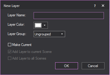
3Type a new name for your layer (for example, “Stage”).
4Choose the color for the objects in the Layer, from the Layer Color color picker box.
5By default, the new layer is ungrouped but you may choose to set the new layer as part of a group if available from the Layer Group drop-down.
6Choose from the options: Vivien maintains this setting for the next layer that you create.
nMake Current sets the new layer as the current active layer.
nAdd Layer to current Scene adds the new layer to the current active Scene.
nAdd Layer to all Scenes adds the new layer to all the Scenes.
7Click OK.
8To make a layer and all objects on the layer visible on the plot and in virtual views, select the Visible icon. If not selected, the layer is not visible and is not, therefore, editable.
9To make a layer and all objects on the layer editable on the plot and in virtual views, select the Editable icon. If not selected, the layer is not editable and is not, therefore, visible.
Tip: You might want to deselect a layer when you are finished working with it to avoid possible errors while working on other parts of the plot. This is similar to freezing in AutoCAD.
10To change the color of the layer, click Color Select.

Note: It is recommended that you select different colors for each layer so as to easily identify the layers on the plot.
Tip: To learn more about the colors in which objects can appear, see “Rules for objects’ colors in Vivien”.
11To change the line weight of the selected layer, choose the applicable thickness from the Line Weight drop-down box. If you leave Default selected, the line weight from the Object Settings tab is applied to the selected layer. The line weight that you select applies to all objects on this layer (including library objects, pipes, and truss) and is visible in all Wireframe views in all modes.
12To set a different Print Color for a layer (while preserving the actual Layer Color), choose the color from the Color Select box under the Print column. By default, the Print Color is set to the Layer Color, and this is identified by the Color Select box shown with a checker pattern to identify them as the same. When the Print Color is set to a different color, the selected color will appear in the Color Select box.
Note: The print color will be displayed in Layouts and New Plots when it is set to a color.
13Select the checkbox on the Greyscale column to override the color of the layer and display it in greyscale, while preserving the actual layer color. This will display it in greyscale, while preserving the actual layer color. This will display the layer(s) as grey, while another layer, which may be more important in the plot, will be displayed in their color and be more visible in the plot.
Note: When layer(s) are set in greyscale, you can change how the objects in the layer(s) will be displayed in the General tab in User Options. See “User Options”.
14To view the properties of a layer (for example, name, color, and inventory of objects drawn on the layer), click the Layer Properties icon. For more information on these properties, refer to “Layer properties”.
|
The Layer Properties button. |
15Before closing the dialog, set your current layer by highlighting it, and then clicking Set Current. Alternately, you can set the current layer buy double clicking in the first column on the left, beside a layer name.
|
The Set Current button. |
Note: The current layer is the layer that you are working on at the moment – any object that you draw is placed on this layer and assumes the layer's default properties when it is drawn. A check mark appears beside the name of the current layer.
16To view and modify the scenes in which a layer is included, select a layer, and then click Scenes. For details, see “Scenes”.
|
The Scenes button. |
17Click OK to close the Layers dialog.
Notes:
nTo quickly sort the layers within the layer database, click the appropriate column heading in the Layer Database dialog box. For example, click the Editable column heading to sort the layers by edit setting; that is, those layers marked as editable appear at the top of the list in alphabetical order.
nHow columns appear in the Layer Database can be edited. The order of columns can be changed by clicking on a column header and dragging it left or right to the desired position.
nTo show/hide columns, right-click anywhere in the table area, then select or deselect the columns from the displayed list.
18.To freeze columns, right-click on the heading of the column and select Freeze Columns in the displayed list.

After you add layers, you can merge two or more of them together if you decide that you need to combine them.
To merge layers
1From the Managers menu, choose Layer....
2In the Layer Database window, hold CTRL and click to select the layers that you would like to merge together.
3With the layers selected, click the Merge Layers button .
|
The Merge Layers button. |
Result: Vivien asks you to specify the Target Layer, or the layer to which the additional layers will be merged.

4From the drop-down box, select the target layer, and then click OK.
Result: The layers are merged, and you will see only the target layer (the one you chose to merge other layers into).
You can highlight the current/active layer automatically, by keeping only the current layer displayed in its layer color while all the other layers are in greyscale.
To enable layer highlight
1From the Managers menu, choose Layers.
2In the Layer Database window, highlight a layer.
3Click the Set Current button. Alternately, you can double click the column on the left beside the layer name.
4Click the Layer Highlight button.
|
The Layer Highlight button. |
Result: The highlighted layer will be displayed in its layer color and all the other layers will be in greyscale.
Note: You can change the color of the highlighted layer in the General tab in User Options. See “User Options”.
All layers have properties that describe the appearance of the layer. Objects that reside on the layer inherit the properties of the layer by default unless you decide to override the values. For more information on overriding object properties, see “Customizing object properties”.
General tab
Options on the General tab affect the selected layer’s color, line weight and visibility.
Note: To learn more about coloring objects, see “Rules for objects’ colors in Vivien”.
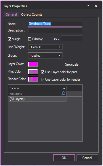
nName: The name of the selected layer.
nDescription: A description of the selected layer.
nVisible: Check this option to make the selected layer visible on the drawing and in Virtual Views. Modifying the property here changes it on the Layer Database dialog box.
nEditable: Check this option to make the selected layer editable on the drawing and in Virtual Views. Modifying the property here changes it on the Layer Database dialog box.
nTag: A descriptive tag applied to the layer. Used for sorting and categorizing information.
nLine Weight: From the drop-down box, choose Default to set the layer’s line weight to the default value specified on the Object Settings tab. For more information, refer to the “Object Settings tab”. If preferred, you can also choose a specific line weight for the layer. The value is used as the line weight for all the objects that reside on the specified layer (including library objects, pipes, and truss), unless otherwise modified. To modify the line weight of an object, refer to the “General tab”.
nGroup: From the drop-down box, choose the Layer Group where this layer will be set into.
nLayer Color: Specify the color of this layer to set the color of all the objects that are displayed in this layer in all Wireframe views.
nGreyscale: Select this checkbox to override the color of the layer and display this layer in greyscale while preserving the actual color.
nPrint Color: Specify a different color for objects that reside in the selected layer when printing the document. Select the Use Layer color for print checkbox to use the same layer color when printing the document. When the print color is the same as the layer color, the Color Select box will show a grey checker pattern to identify them as the same. When the print color is different from the layer color, the Color Select box will show the set color.
Note: The print color will be displayed in Layouts when it is set to a color.
nRender Color: Specify a different color for objects that reside in the selected layer when rendering in Virtual View. Select the Use Layer color for render checkbox to use the same layer color when rendering objects in this layer. When the render color is the same as the layer color, the Color Select box will show a grey checker pattern to identify them as the same. To modify the object color for rendering, refer to “General object properties”.
nScene: The scenes that the layers appear in.
Object Counts tab
Entries on the Object Counts tab indicate the total number of objects that reside on the selected layer. Values on this tab are view only.
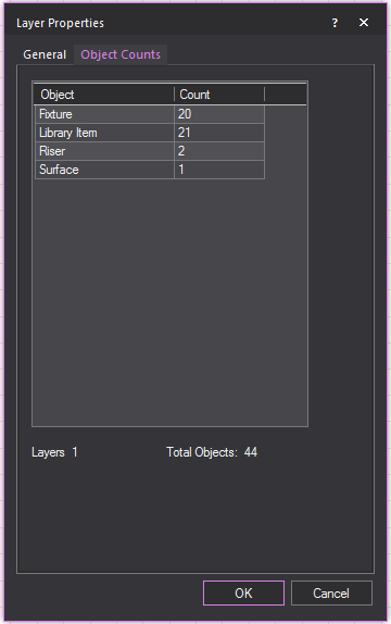
Once layers are created, descriptions and tags can be added to the layers to easily sort the layers and show what they are used for. The Description column can contain a description of your layer, or any notes you wish.
Note: If you import an AutoCAD file containing text in its Description column, the text will be imported into the Description column in Vivien.
To add descriptions and tags to layers
1From the Managers menu, choose Layers.
Result: The Layer Database dialog box is displayed.

2In the Layer Database window, click in the Description or Tag field next to the layer you want to add information to.
3Type in the information in the field.
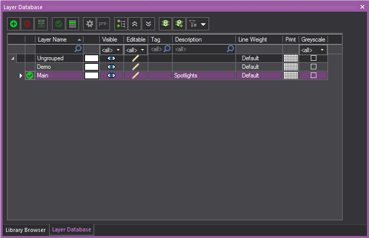
Result: The layer will have descriptive information added.
The prefix tool is used to add a prefix to the existing name of all the selected layers.
To add prefixes to layers
1From the Managers menu, choose Layers.
Result: The Layer Database dialog box is displayed.

2In the Layer Database window, select the layers you want to add a prefix to.
3Click the Prefix button.
Result: The Change Layer Prefix window will appear.

4In the Change Layer Prefix window, enter the prefix you want to use.
5Click OK.
Result: The selected layers will now have the chosen prefix before their name.
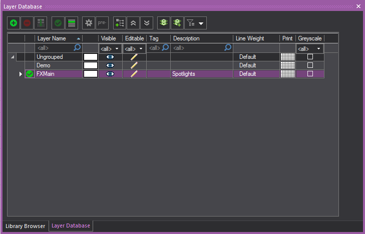
When using scenes, the Layer Database can have filters applied so that only layers found in the scene will be visible.
To filter the Layer Database
1From the Managers menu, choose Layers.
Result: The Layer Database dialog box is displayed.

2In the Layer Database window, click the Filter icon.
|
The Filter button. |
3In the filter list, select Layers in the Current Scene.
Result: Only layers in the current scene will be visible in the Layer Database
You must remove all objects from a layer before you can delete it. You cannot delete the current layer.
To delete a layer
1Select all of the objects on the layer that you want to delete and delete them or move them to another layer.
2From the Managers menu, choose Layers.
Result: The Layer Database dialog box opens.
3Ensure that the layer you want to delete is not set as the current layer.
4Select the layer in the list.
5Click Delete.
6Click OK.
Tips:
nThe Layer toolbar gives you quick access to all existing layers and the Layer Database. Click the tool on the left end of the Layer toolbar to access the Layer Database.
|
The Layer Database button. |
nUse the layer list in the Layer toolbar to quickly set the current layer. If objects are selected when you do this, those objects are moved to the selected current layer.
A Layer Group is a selection of layers that are organized into a group in the Layer Database window. One or more layers can be selected and set into a Layer Group with a specified name. Properties that are set to a Layer Group will be assigned to all the layers within the Layer Group. Layer Groups are created, viewed and modified in the Layer Database window. The Layer Group feature is enabled or disabled in the Document Options window.
The ungrouped layers, by default are listed under the group name “Ungrouped”, which can be renamed like any other Layer Group.
In the Layer Database window, the position of the “Ungrouped” group can be set to either top or bottom of the displayed list.
You can also right-click on the Layer Database window and click Layer Groups from the list to toggle the display of Layer Groups in the Layer Database.
To create new Layer Groups
1From the Managers menu, choose Layers.
Result: The Layer Database dialog box is displayed with the layer groups enabled and displayed.
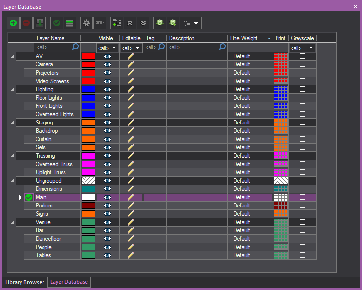
Tips:
nYou can rename the Ungrouped layer, by clicking the Ungrouped cell and typing the new name.
nYou can reposition the Ungrouped layer, by right-clicking anywhere in table and choosing Options and selecting Top or Bottom in the Grid Options window. You can also go to the General tab in the User Options of the Document Options window, see “User Options”.
2Press and hold CTRL and select one or more layers.
3Click the New Group icon.
|
The Layer Group button. |
4Type a new name for your Layer Group.
5Click OK.
Result: The new Layer Group with all its layers is added to the list.
6To make all layers in the Layer Group visible or invisible on the plot and in virtual views, select the Layer Group, then click the Visible icon. All the layers in the Layer Group will not be editable if not visible.
7To make all the layers in the Layer Group editable or not-editable on the plot and in virtual views, select the Layer Group, then click the Editable icon.
8To change the color of all the layers in the selected Layer Group, click Color Select. All the layers in the Layer Group will have the new color.
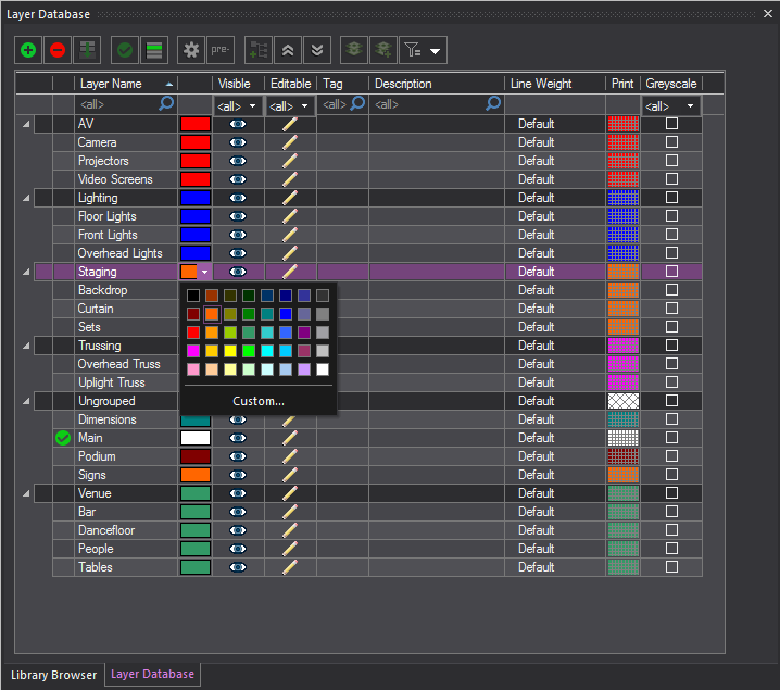
9To change the line weight of all the layers in the selected layer Group, choose the thickness from the Line Weight drop-down box. If you leave Default selected, the line weight from the Document Options window is applied to all the layers in the selected Layer Group. The specified line weight sets the thickness for all the object symbols in the associated layers (including library objects, pipes, and truss) in the Layer Group, defining how they will appear in all the Wireframe views and printed Layouts.
10To set a different Print Color for the selected layer group (while preserving the actual Layer Color of the group), choose the color from the Color Select box under the Print column. The print color selected for the layers in the group will be displayed in Layout and New Plots.
11Select the checkbox on the Greyscale column to override the color of the layer group and display it in greyscale, while preserving the actual layer group color. This will display the layer(s) in the layer group as grey, while another layer, which may be more important in the plot, will be displayed in their color and be more visible in the plot.
Note: When layer groups are set in greyscale, you can change how the objects in the layer groups will be displayed in the General tab in User Options. “User Options”.
12On the list of Layer Groups, click the arrow at the far left of each layer to expand or collapse a single Layer Group.
13Click the Collapse All button to display only the Layer Groups.
|
The Collapse All button. |
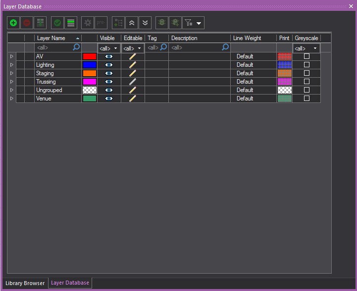
14Click the Expand All button to display the Layer Groups and all the Layers.
|
The Expand All button. |
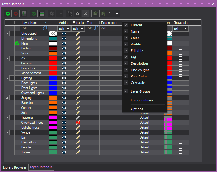
Notes:
nThe use of Layer Groups can be switched off from the Layer Database window. Right-click the table area and from the list of columns that appear, clear Layer Groups. This links to the General tab in the Document Options window and disables the Enable Layer Groups option. Only the list of layers will be displayed in the Layer Database window.
nThe order of how the columns appear in the Layer Database can be changed by clicking on a column header and dragging it left or right to the desired position.
nTo show/hide columns, right-click anywhere in the table area, and then select or deselect the columns from the displayed list.
nTo freeze columns, right-click on the heading of the column and select Freeze Columns in the displayed list.
nBy default, ungrouped layers are listed under the group name Ungrouped, which can be changed, and listed on top or bottom of the list of layers.
nTo change the name, click the name and type the new name.
nTo change the position, right-click anywhere in the table and click Options. Select Top or Bottom in the Grid Options window. You can also go to the General tab in the User Options of the Document Options window. See “User Options”.
Descriptions and Tags can be added to a Layer Group which will be displayed to all the layers of the selected Layer Group.
To add descriptions and tags to Layer Groups
1From the Managers menu, choose Layers.
Result: The Layer Database dialog box is displayed.

2In the Layer Database window, click in the Description or Tag field in the row of the Layer Group you want to add information to.
3Type the information in the field.
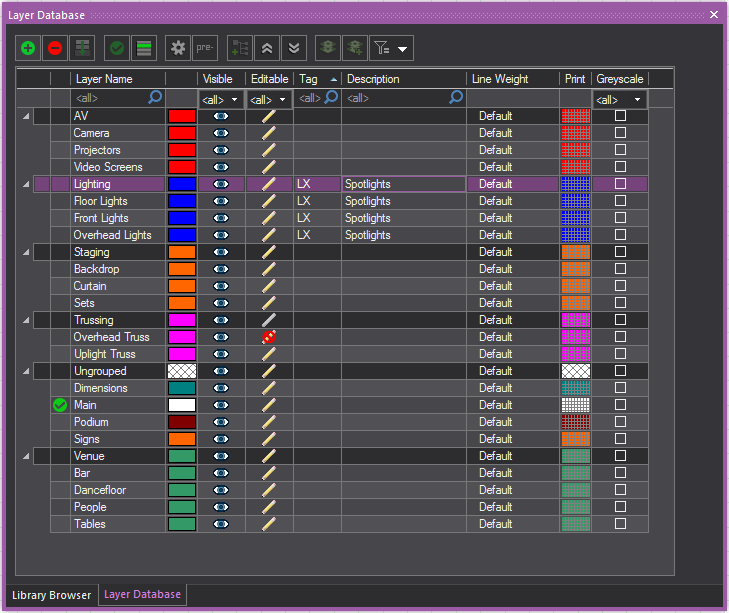
Result: The Layer Group and all the layers associated will have the descriptive information added.
To move a layer from one group to another
1From the Managers menu, choose Layers.
Result: The Layer Database dialog box is displayed.

2In the Layer Database window, highlight one or more layers you want to move.
3Click and drag the highlighted layer/s (NOT the active layer) into another layer group where you want the layer/s transferred.
Deleting the Layer Group will remove the Layer Group from the Layer Database. All the layers of the deleted Layer Group will be ungrouped and returned to the Ungrouped group. All the settings of the deleted Layer Group will be removed from all the ungrouped layers.
To delete a layer group
1From the Managers menu, choose Layers.
Result: The Layer Database dialog box is displayed.
2Select the Layer Group from the list.
3Click the Delete icon.
|
The Delete button. |
Result: The Warning dialog is displayed to inform that the layers in this Layer Group will return to the Ungrouped Group. Select the checkbox Always move associated layers to the Ungrouped Group when Layer Group is deleted and the Warning dialog will not appear again.

4Click Yes.
Scenes are collections of layers used to organize the drawing. A scene may contain one or more layers.
Hiding a scene hides all the layers assigned to that scene. By organizing the layers and scenes in your drawing you can quickly switch between different room setups.
By default Vivien creates two initial scenes: Current Layer Only and All Layers. You cannot delete these scenes.
You can use a keyboard hotkey to activate and switch between scenes in your drawing. A hotkey is automatically assigned to a new scene upon creation.
To create a new scene
1From the Managers menu, choose Scenes.
Result: The Scene Database window appears.
Notes:
nThe default scenes All Layers and Current Layer Only are always displayed on top of the list, followed by all User-created scenes in ascending or descending order.
nThe Ungrouped group of layers are displayed at the top or bottom of the list, as set in the Document Options > General tab.
nThe Scene Database window will remember its last size when you reopen it.

2Click New to create a new scene.
3Type the name of the new scene and then click OK.
Result:
nThe layers associated with the scene are displayed in the Layers Included box with selected checkboxes.
nThe new scene is added to the Scenes box with its corresponding Hotkey (CTRL+NUMPAD <1-9>)that was automatically assigned upon creation and displayed in a separate column. See the “Dynamic scene switching” section if you want to change the Hotkey of a scene.
4On the Scenes box, click on a scene or multiple scenes, and on the Layers Included box, select the checkbox of each layer you want to include in the selected scene(s). For more information, refer to “Layers”.
Tip: Press and hold CTRL and click on the scenes to select multiple scenes which you can edit or delete together.
Notes:
nTo copy a scene, see “To clone a scene in scene database”.
nTo rename a scene, select the scene, and then click Rename.
nTo remove a scene, see “To remove a scene from scene database”.
5Click Set Current to activate your new scene. If the current layer is not in the current scene, you cannot add any objects.
6Click OK.
Tips:
nThe Scenes toolbar gives you quick access to all existing scenes and the Scenes database. Click the tool on the left end of the Scenes toolbar to access the Scene Database window.
|
The Scenes button. |
nPay special attention to the "(Current Layer Only)" scene. As its name implies, this scene isolates the current layer and shows only the items this layer contains. This can be extremely useful when working with a complex object that requires editing, texturing, and so on, or when adjustments need to be made to a complex show in which objects overlap, or other complicated drawing scenarios.
To clone a scene in scene database
1On the Scenes box in the Scene Database window, select a scene (or multiple scenes) that you want to copy.
2Click the Copy button.
|
The Copy button. |
3Type the name for the cloned scene.
4Select the Set as Current Scene checkbox if you want the cloned scene to become current.
5Click OK.
Result: The cloned scene is added to the Scenes box in the Scene Database window. The copied scene has the same properties of the selected scene.
To remove a scene from scene database
1On the Scenes box in the Scene Database window, select a scene (or multiple scenes) that you want to remove.
2Click the Delete button.
|
The Delete button. |
3Click Yes on the delete confirmation dialog box that appears.
Result: The selected scene is removed from the Scenes box in the Scene Database window.
A keyboard hotkey is automatically assigned to a new scene upon creation and displayed in the Scenes box on the Scene Database window. You can use the keyboard hotkeys (CTRL+NUMPAD <1-9>)to activate and switch between scenes. You can also change the hotkey settings displayed on the Scenes box.
To change or disable a hotkey of a scene
1On the Scenes box of the Scene Database window, select a scene with the hotkey setting (CTRL+NUMPAD <1-9>) that you wish to change.
2Click on the drop-down arrow on the Hotkey column of the selected scene.
3From the Hotkey drop-down list of the selected scene, select the new hotkey setting (CTRL+NUMPAD <1-9>) or select <None> to disable.
 Plan view
 Left view
 Right view
 Front view
 Back view
 3D view


