
Editing
objects
Selecting objects
You must select objects before you can
manipulate them.
- Selected objects display with dotted lines and
a white box at the insertion point.
- Selected light fixtures and projectors are filled
in green.
Use the following table to identify the
selection method for objects.
Desired
action |
Selection
method |
Select a single object. |
Note:
You must click a line on the object. Clicking inside the
object does not select it. |
Select a single fixture. |
In Drawing Wireframe, click on or inside
the fixture symbol’s outline. In 3D view, click the symbol’s outline
to select the fixture |
Select multiple objects. |
Press and hold the CTRL key
while clicking the desired objects. Draw a box from left to right to select
all objects fully within the box. Draw a box from right to left to select
all objects fully within the box, as well as the objects partially
contained in the box. |
Select all the objects on the screen. |
|
Select all the objects on the current
layer. |
or
|
Restore selection to the objects
previously selected. |
|
Select the last object created. |
|
Select all the objects on one or
more layers or in layer groups. |
|
Select only specific objects from
within already selected objects. |
In
Drawing Wireframe, select multiple objects. Press and hold
SHIFT, and right-click. The
right-click menu's
> and/or
> menus only show visible and selectable objects from the
current selection set (as opposed to all visible and selectable
objects in the file - which is what these menus show when
SHIFT is not used). |
Invert Selection |
From menu,
choose and then click
. Press CTRL+I to
deselect all editable objects currently selected, and consequently
select all the other editable objects that were previously
not selected.
Note:
applies only to fixtures in Lighting Wireframe/Quad and Virtual
View. |
Select all of one type of lighting
fixture or all lighting fixtures in your file. |
|
Cycle select multiple objects. |
Press SHIFT before
clicking to select the object. When is active, Cycle On appears in the Vivien
Status Bar. To select the object, you must click on a spot
where two or more lines overlap or intersect. To continue
selecting, keep pressing to
cycle through all items that share the area where you clicked. |
Invert
selection
This feature is helpful if you want to
deselect all the currently selected editable objects (in Wireframe), and
consequently select all objects that were previously not selected.
- From the menu, choose and
then click to activate
invert selection, or press CTRL+I, which
applies to all objects displayed in Wireframe.
- or
CTRL+I applies only to fixtures
displayed in Lighting Wireframe and Virtual View.
To use invert selection
For example, if your drawing has a total
of 10 objects, and 4 objects out of the 10 are currently selected. From
the menu, choose and then click ,
or press CTRL+I to activate invert selection.
Result: The 4 selected objects will be deselected
and the other 6 objects that were previously not selected, will be selected
automatically.
Undoing/Redoing actions
You can reverse your last series of actions
using the menu command. The name of
the command changes depending on what
the last action was (for example, if the last action was a operation,
the command is ). reverses the series of actions
that you performed since you opened the document, including those actions
that you performed before you last saved the document. If you cannot reverse
the last action, the command is grayed.
If you decide that you did not want to
undo an action, use the command. Similar
to the command, the name of the command changes depending on what the
last undo action was.
To use the Undo tool
From the menu,
choose .
or
Click the Undo tool
on the Edit toolbar. The last action
you performed is reversed.
 The
Undo button.
The
Undo button.
To use the Redo tool
From the menu,
choose .
or
Click the Redo tool
on the Edit toolbar.
 The Redo button.
Result: The last undo action you performed is reversed.
Repeating
the last command
To repeat the last command
From the menu,
choose .
or
Click the Repeat tool
on the Edit toolbar.
 The
Repeat button.
The
Repeat button.
Result: The last command you performed is repeated.
Deleting objects
There are two ways to remove objects from
your drawing: using the command
and using the command. The command
places the object on the clipboard so it is available to be pasted.
To delete an object
- Select the object(s) to be deleted.
- From the menu,
choose .
or
Click the Delete tool
on the Edit toolbar.
 The
Delete button.
The
Delete button.
Result: The object is removed from the drawing and
the Event Resources.
To cut an object
- Select the object(s) to be deleted.
- From the menu,
choose .
or
Click the Cut tool
on the Edit toolbar.
 The
Cut button.
The
Cut button.
Result: The object is removed from the drawing and
the Event Resources and placed on the clipboard.
Grouping/Ungrouping
objects
Grouping objects together ensures that
they are always selected (and edited) as one. For example, you might want
to group a projector with the table or riser it sits on. If you relocate
the projector in the drawing, the riser automatically moves with it, saving
you time and work.
In order to use Groups effectively, it
is important to understand how they operate in Vivien (which may be different
than in other software). To that end, ensure that you have read through
the “Groups are objects that exist on layers”
section.
To group objects
- Select the objects to be grouped.
- From the menu,
choose .
or
Click the Group tool
on the Modify toolbar.
 The Group button.
Result: The Dynamic Group Outline appears to indicate
that the selected objects have been Grouped.
Dynamic
Group Outline is a dashed framing outline enclosing all objects
within a Group. The color of the outline is the same as the color of the
Layer where the Group belongs. Dynamic Group Outline will continue to
appear every time a Group is selected, until the Group is Ungrouped. For
more information, see “Dynamic group outline”.
To ungroup objects
- Select the grouped objects.
- From the menu,
choose .
or
Click the Ungroup tool
on the Modify toolbar.
 The
Ungroup button.
The
Ungroup button.
Result: The objects are ungrouped and the Dynamic
Group Outline disappears.
Objects located on different layers can
be grouped together but the resulting group only exists on one layer—the
current layer when initially created.
To change or view the layer
of a group
- Select the object(s) for which you want to view
the grouping.
- Right-click and select .
 The
Properties button.
The
Properties button.
- Click the Group tab.
Result: The layers for the objects in the group are
listed with the layer for the group highlighted.
Note: By default, the group assumes the current
layer when initially created.
- If you want to group the objects on a different
layer, select the layer from the list.
Selection
Sets
You can group non-fixture objects and create
Selection Sets shortcuts in the Selection Sets shortcut
bar in the Wireframe, Quad and Virtual views. Selection Sets apply to
any and all drawn objects and objects inserted from the
Library Browser, which include Groups
and Truss.
Selection Sets are NOT the
same as Groups because they only save which particular objects are selected,
and the order in which they are selected.
To create a Selection Set
- Select the objects you want to group and select
with a shortcut.
- On the shortcut bar, click Selection
Sets.
- Right-click on the open space on the Selection
Sets shortcut bar, and choose from the popup menu.
Result:
The Enter new selection set name dialog box
appears.
- Type a name for the new selection set.
- Click OK.
Result: The new Selection Set shortcut appears on
the Selection Sets shortcut bar.
Moving
objects
Vivien supports two types of move commands:
relative and absolute.
Absolute
coordinates are relative to the origin of the drawing. An absolute move
is defined as moving an object from one specific point to another.
A relative
move is defined as moving an object to a destination relative to its original
position.
To move an object using the mouse
- Select the object(s) to be moved.
- Hover the cursor over the object until a gray
box appears at the base of the cursor.
- Click and drag the mouse to the new position and
then release to finish the move.
To move an object using absolute values
- Select the object(s) to be moved.
- From the menu,
choose .
or
Click the Move tool
on the Modify toolbar.
 The Move button.
- Click to set the base point for the move.
or
Press ENTER
to automatically select the object's insertion point as the base point
for the move.
or
Type the coordinates of the base point
and press ENTER. Type a comma between each
coordinate. When you start typing, the Command Line
toolbar opens, if it is not open already.
- Enter the new coordinate location for the base
point, and then press ENTER.
Tip: You can change only one or two coordinates
to an absolute location while keeping the other coordinates as they are.
Example: If you want an object to move to a height
of Z=10 but you don’t know the X and Y coordinates. Start the command
and type “x,y,10” in the Command Line after
picking the base point.
To move an object using relative values
- Select the object(s) to be moved.
- From the menu,
choose .
or
Click the Move tool
on the Modify toolbar.
 The Move button.
- Type @ and the
distances to move the object and press ENTER.
For example, to move an object 2’0” stage right (X axis) and 3’0”
off the floor (Z axis), type the following and then press ENTER:
@2’,0,3’
.
To move an object using distance and direction
- Select the object(s) to be moved.
- From the menu,
choose .
or
Click the Move tool
on the Modify toolbar.
 The Move button.
- Type @, the distance,
the < sign and the direction (as an angle, positive or negative)
to move the object and press ENTER.
For example, to move an object 3’6” to the left, type the following,
and then press ENTER: @3’6”<-180.
Distributing objects
A group of objects can be selected and
then distributed in a straight line between two points.
To distribute objects between two points
- Select the objects to be distributed.
From the menu,
choose and then click
or
Click the Between
Two Points tool on the Modify toolbar.
 The Between Two Points button.
- Click on the drawing to set the first distribution
point.
- Click on the drawing to set the second distribution
point.
Result: The objects will be distributed evenly in
a straight line between the two chosen points.
Rotating objects
Objects can be rotated around a base point.
This allows you to place objects on angles in your drawing or to reorient
objects place from the Library.
To rotate an object
- Select the object(s) to be rotated.
- From the menu,
choose .
or
Click the Rotate tool
on the Modify toolbar.
 The
Rotate button.
The
Rotate button.
- Press ENTER on
your keyboard to rotate the object from its insertion point, OR click
to set the center point for the rotation, OR
type in the coordinates of the center point for the rotation, and
then press ENTER.
- Enter the rotation angle and press ENTER,
or drag the mouse, and then click to enter the rotation angle. For
example, to rotate an object 45 degrees, type 45 and press .
Rotating objects in place
You can rotate multiple objects around
their respective insertion points to place them all at the same angle
in your drawing.
To rotate multiple objects in place
- Select the objects to be rotated.
- From the menu,
choose .
- Click to set the base point used for the rotation
angle.
or
- Type in the coordinates of the base point, and
then press ENTER.
Note: The base point is only used to help determine
the angle, as each object is rotated around its own insertion point.
- Type the rotation angle, and then press , or move the mouse and click to set the
rotation angle. For example, to rotate objects 45 degrees, type 45,
and then press .
Resetting object orientation
To reset the rotation of objects
- Select the objects whose rotation needs to be
reset.
- From the menu,
choose .
Result: The object’s orientation will be reset to
its default setting.
Mirroring objects
The command
duplicates and reverses an object, inserting it the same distance from
an axis line as the original.
Notes:
- Pipes, truss (including fixtures hanging on them)
and fixtures inserted on the floor can be mirrored. “Mirroring pipes” and
“Mirroring
truss” for more information.
- When mirroring Text Label objects, the Text Label’s
position/rotation, anchor position, callouts and arrows will be mirrored
across the mirror plane, but the text will always face the screen
and will not be reversed.
To insert a mirrored object
- Select the object(s) to be mirrored.
- From the menu,
choose .
or
Click the Mirror tool
on the Modify toolbar.
 The
Mirror button.
The
Mirror button.
- Click on the drawing to set the first axis point.
- Click on the drawing to set the second axis point.
Result: The mirrored object is copied, reversed from
the origin based upon the axis drawn.
Copying objects
There are two ways to make copies in Vivien:
using the and commands,
and using the command.
The command
makes multiple copies of an object and distributes them evenly along a
line, arc, grid or random pattern.
For details about cloning fixtures along
a pipe or truss, see “Hanging
multiple fixtures”.
To copy and paste
- Select the object(s) you want to copy.
- From the menu,
choose .
or
Click the Copy tool
on the Edit toolbar.
 The Copy button.
- From the menu,
choose .
or
Click the Paste tool
on the Edit toolbar.
 The
Paste button.
The
Paste button.
To perform a linear clone
- Select the object you want to clone.
- From the menu,
choose and then click
.
- Click a point on your drawing or type coordinates
to specify the direction and interval/length of the linear clone.
Example: To place a copy of the selected object every
5’ at a 45 degree angle type the following and then press ENTER:
@5’<45
Result: The Clone Linear window appears.
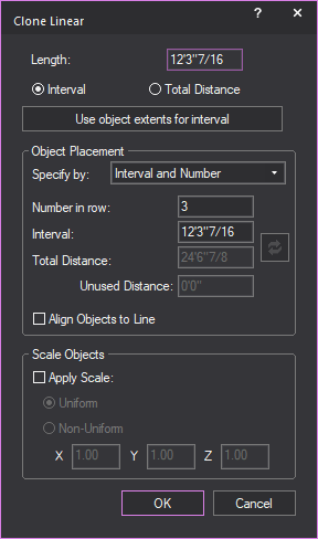
- In the Clone Linear window, in the Length section,
select whether the section drawn in Step
3 will be an Interval,
or the Total Distance
of the clone.
- If you selected Interval,
you may click Use object extents for interval to
automatically populate the Interval text box with the dimensions of
the selected object.
- In the Object Placementsection, select which values will be available
for editing.
Notes:
- When performing a clone, the value not chosen
for editing is calculated automatically by Vivien and is grayed out.
- To undo changes made to the clone values, click
Reset button.
 The Reset button.
- In the Number in row box,
type the total number of copies desired (this includes the original
object).
- In the Interval box,
type the interval distance between objects.
- In the Total Distance box,
type the distance from the first to last object.
- Select the Align Objects
to Line checkbox, to align objects to the set line.
- If you want to scale the copied objects, select
the Apply Scale checkbox in the Scale Objects section
and choose the scaling options that are available for editing.
- Select the Uniform radio
button to display all the copied objects in one size.
or
Select the Non-Uniform radio
button to display the copied objects in different sizes.
- If Uniform was
selected, type the value in the X box
to specify a uniform scale factor of the last copied object in the
clone. The sizes of the copied objects multiply uniformly in increments
from first to the last copied object.
or
If Non-Uniform was
selected, type the values in the X, Y and Z boxes
to specify the scale factors of the last copied object in the clones.
The sizes of the copied objects multiply in increments from first to the
last copied object.
- Click OK.
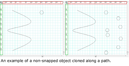
To perform a
clone along a path
Perform this procedure to clone a selected
object along a path that shares the same design as a line, arc or spline.
- Draw a line, arc or spline that will act as a
path for the cloned object.
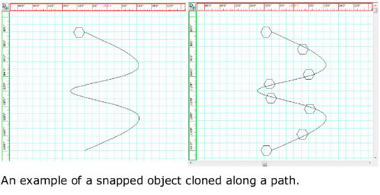
- Select the object you want to clone.
Note: The object will be cloned from its current
location. To clone the object on top of the path, snap the object to the
end point of the path.
- From the menu,
choose and then click .
Result: The Clone Along Path
window appears.
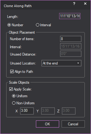
- Under Length, select
one of the two options:
- Number:
To clone a specific number of objects along the path.
or
- Interval: To
clone the object at specific intervals along the path.
Note: Objects can be cloned a specific number of
times, or at specific intervals along the path. When one option is selected,
the other will become unavailable.
- Under Object Placement,
if Number was
selected previously, enter the
number of time the object is to be cloned in the Number
of items field. If Interval was
selected, enter the distance at which the object will be cloned in
the Interval field.
Note: If Interval was
selected, the Unused Distance field will show how much
space along the path will be unused with no objects cloned.
- Select from the Unused Location drop-down
menu where the unused space should be along the path.
- To have the object clones aligned to the path,
select the Align to Path checkbox.
- If you want to scale the copied objects, select
the Apply Scale checkbox in the Scale Objects section and choose the scaling
options that are available for editing.
- Select the Uniform radio
button to display all the copied objects in one size.
or
Select the Non-Uniform radio
button to display the copied objects in different sizes.
- If Uniform was
selected, type the value in the X box
to specify a uniform scale factor of the last copied object in the
clone. The sizes of the copied objects multiply uniformly in increments
from first to the last copied object.
or
If Non-Uniform was
selected, type the values in the X, Y and Z boxes
to specify the scale factors of the last copied object in the clones.
The sizes of the copied objects multiply in increments from first to the
last copied object.
- Click OK.
Result: The object will be cloned in a patter based
on the path.
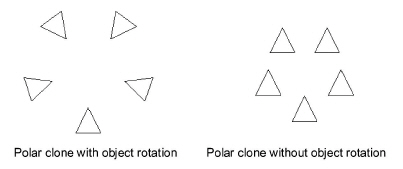
To perform a polar clone
- Select the object you want to Clone.
- From the menu,
choose .
- Click a point that represents the center of the
circle around which the objects will be cloned.
- In the dialog box that opens, type the total number
of copies desired (this includes the original object).
- Specify the total angle in degrees to fill with
copied objects.
- Select the Rotate Objects checkbox
if you want the copied objects to rotate as they are pasted around
the center of the circular clone, as shown below.
- Click OK.
To clone objects in a grid
pattern
Perform this procedure to copy and paste
the selected object in a grid pattern in the direction and at the distance
that you specify.
- Select the object that you want to clone.
- From the menu,
choose .
Result: The Grid Clone window
appears.
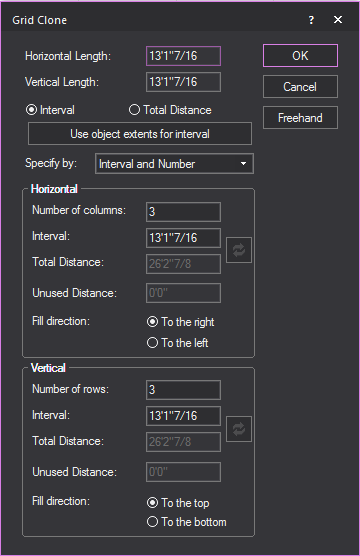
- Select whether the horizontal and vertical lengths
will be an Interval, or the Total
Distance of the clone.
Note: Click Freehand to
manually draw the horizontal and vertical lengths of the gird clone.
- If you selected Interval,
you may click Use object extents for interval to
automatically populate the Horizontal
Interval and
Vertical Interval text
boxes with dimensions of the selected object.
- Specify which values will be available for editing.
Notes:
- When performing a clone, the value not chosen
for editing is calculated automatically by Vivien and grayed out.
- To undo changes made to the clone values, click
the Reset button.
 The Reset button.
- In the Number of columns box,
type the number of columns in the grid.
Note: This value includes the original object(s)
as the first “column” of the grid. For example, if you type 3, the object
is copied and pasted twice beside the original object in the direction
and at the distance that you specify.
- In the Interval box,
type the spacing between each horizontal object in the grid.
- In the Total Distance box,
type the distance between each horizontal object in the grid.
- Select the Fill direction in
which you want the object(s) to be cloned horizontally in the grid,
either To the right
or To the left of the original
object.
- In the Number of rows box,
type the number of rows in the grid.
Note: This value includes the original object(s)
as the first “row” of the grid. For example, if you type 3, the object
is copied and pasted twice above or below the original object at the distance
that you specify.
- In the Interval box,
type the distance between each vertical object in the grid.
- In the Total Distance box,
type the distance between each vertical object in the grid.
- Select the Fill direction in
which you want the object(s) to be cloned in the grid vertically,
either above or below the original object.
- Click OK.
To clone object in a random pattern
Clone fill is used to take an object and
randomly clone it in a defined space.
- Select the object that you want to clone.
- From the menu,
choose .
Result: The Random Fill window
appears.
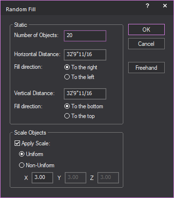
- In the Number of Objects box,
type the number of cloned objects to appear.
- In the Horizontal Distance box,
type the horizontal distance of the defined space.
- Select the Fill direction in
which you want the object(s) to be cloned horizontally, either To the left or To
the right of the original object.
- In the Vertical Distance box,
type the horizontal distance of the defined space.
- Select the Fill direction in
which you want the object(s) to be cloned horizontally, either To the bottom or To
the top of the original object.
- If you want to scale the copied objects, select
the Apply Scale checkbox in the Scale Objects section and choose the scaling
options that are available for editing.
- Select the Uniform radio
button to display all the copied objects in one size.
or
Select the Non-Uniform radio
button to display the copied objects in different sizes.
- If Uniform was
selected, type the value in the X box
to specify a uniform scale factor of the last copied object in the
clone. The sizes of the copied objects multiply uniformly in increments
from first to the last copied object.
or
If Non-Uniform was
selected, type the values in the X,
Y, and Z boxes
to specify the scale factors of the last copied object in the clones.
The sizes of the copied objects multiply in increments from first to the
last copied object.
- Click OK.
Scaling objects
The command
changes the size of the object(s). The
command applies to a library object, an imported object, and some primitive
objects.
When you use from
the menu a selected 2D or 3D primitive
object, it multiplies the scale factor specified, calculates a new dimension
for the primitive object and updates the value in its properties. Whenever
an object is scaled, the scale factor of the resulting scaled object in
its new size will always be equal to 1 again.
When you use from
the menu and specify a scale factor
equal to 1, the size of the selected object will not change.
If you want to reset the scaled object
back to its original or normal size, select the object, and then choose
from the menu.
To use the command on imported objects which did
not import as single entities, we recommend for you to consolidate the
selected objects first, using Vivien’s Consolidate
Mesh feature. If not consolidated, the relative position and
size of such objects will not be preserved after the
operation is completed.
Notes:
- Fixtures, Truss and Groups cannot be scaled.
- You can enable the Show
Bounding Box for CAD operation option in the Object
Settings tab in the Document Options window
to improve the operation performance when you scale complex objects.
A bounding box appears as a placeholder to complex objects when scaling
or rotating in Wireframe.
To scale one or more objects uniformly
- Select the object(s) to scale.
- From the menu, choose .
Tip: You may also click the Scale button
on the Modify toolbar.
 The Scale button.
- In the Command Line toolbar,
type the scale factor value (for example “2” or “0.5” or “4”, etc)
for a uniform and precise resize.
or
Use the mouse wheel to increase or decrease
the size of the objects for a uniform and experimental resize method;
each notch of the mouse wheel will increase or decrease the object’s scale
uniformly (i.e. on all three axes) by a factor of 0.5.
- On your keyboard, press ENTER.
Result: The size of the selected object changes uniformly
according to the scale factor.
To scale one or more objects with different scale values
in X, Y, Z
- Select the object(s) to scale.
- From the menu,
choose .
Tip: You may also click the Scale button
on the Modify toolbar.
 The Scale button.
- In the Command Line toolbar, type the three (3) values for X,
Y, Z directions.
Example: Type “2,3,1” in the Command
Line to make the selected object 2x wider in the X direction,
3x longer in the Y direction, and the height remains the same as 1x in
the Z direction.
- On your keyboard, press ENTER.
Result: The size of the selected object changes according
to the scale factor for X, Y and Z.
To scale an object by stretching it with click and drag
Note: To scale Library objects (e.g. Tables, Chairs,
etc.) by stretching, Library Snap must be
enabled.
- Select the object(s) to stretch.
- Click and hold on one of the object’s grips, then
drag inwards or outwards.
Result: The mouse pointer becomes an arrow at the
corner, and the selected object changes its size according to the movement
of the mouse.
- Release the mouse when you reach the desired size.
To reset the scaled object back to its original size
- Select the scaled object(s).
- From the menu,
choose .
Result: The size of the selected scaled object changes
back to its original size.
Resizing objects
Certain objects, once drawn, can be resized,
which, in some cases, modifies the shape. Based on the Vivien program
you are in and the objects available in that program, you can resize lines,
risers, cameras, surfaces, and arcs. Resizing changes one or more of the
parameters of the object, such as width, height, or radius.
To resize an object
- Select the object that you want to resize.
Result: Several white boxes appear at the vertices
of the object. These boxes are referred to as “grips”.
- Move your cursor to a grip.
Result: The cursor changes to an arrow.
Note: If you see a gray dotted box beside your mouse
cursor, the object moves instead of being reshaped. Move your cursor so
that only the arrow appears.
- Drag the marker until the object reaches the desired
shape.
- Release the mouse button to set the shape.
Tip: As you move the mouse, the current coordinates
appear at the bottom right of the screen.
Breaking
objects
The Break command
allows you to break a custom drawn object into smaller components.
Note: You cannot break a library object into component
parts.
To break an arc into arcs
- Select the arc you want to break.
- From the menu,
choose and then click .
- Type the number of desired break arcs on the dialog
box that appears.
- Click OK.
Result: The arc is broken equally into the number
of arcs specified.
To break an arc into lines
- Select the arc you want to break.
- From the menu,
choose and then click .
- Type the number of desired break lines on the
dialog box that appears.
- Click OK.
Result: The arc is broken equally into the number
of lines specified.
To break a circle into
arcs
- Select the circle you want to break.
- From the menu,
choose and then click .
- Type the number of desired break arcs on the dialog
box that appears.
- Click OK.
The circle is broken equally into the number
of arcs specified.
To break a circle into
lines
- Select the circle you want to break.
- From the menu,
choose and then choose .
- Type the number of desired break lines on the
dialog box that appears.
- Click OK.
Result: The circle is broken equally into the number
of lines specified.
To
break a line at vertices
- Select the multi-segment line you want to break.
- From the menu,
choose and then choose .
Result: The continuous multi-segment line breaks at
the segment intersections. Each vertex is now an independent line.
To break a line into lines
- Select the line or multi-segment line you want
to break.
- From the menu,
choose and then choose .
- Type the number of desired break lines on the
dialog box that appears.
- Click OK.
Result: The line is broken equally into the number
of lines specified.
To break a solid into faces
- Select the 3D solid you want to break, a riser
for example.
- From the menu,
choose and then click .
Result: Each face of the solid becomes an independent
surface.
To break a solid into lines
- Select the 3D solid you want to break, a riser
for example.
- From the menu,
choose and then click .
Result: Each segment of the solid becomes an independent
line. The 3D solid is no longer a solid.
Tip: Alternatively, to perform a break command,
you can use the Break tool on the Modify toolbar. This is the same as choosing
from the
sub-menu.
 The Break button.
To break using the Specify
dialog
- Select the object you want to break.
- From the menu,
choose and then click .
Result: The Break dialog
box opens.
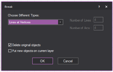
- Select the desired break type from the available
options (depending on the object you have selected to break) by selecting
the appropriate options.
- In the boxes at the top right corner, specify
the number of break lines or arcs if appropriate.
- To replace the original object with the new “broken”
ones, select Delete original objects.
- To place the new “broken” objects on the current
layer, as opposed to the selected object’s original layer, if different,
select Put new objects on current layer.
- Click OK.
Converting objects to other
object types
The command
turns an object into a different kind of object. For example, you can
convert a circle into a circular surface.
To convert a circle into an arc
- Select the circle you want to convert.
- From the menu,
choose and then click .
Result: The circle is converted into a 360 degree
arc. You can drag the marker points out to open the arc.
To convert a circle into a surface
- Select the circle you want to convert.
- From the menu,
choose and then click .
- Type the number of segments to make up the contour
of the surface on the dialog box that appears. The number entered
cannot be 1. The higher the number, the more circular the surface
will be.
- Click OK.
Result: The circle is converted into a surface.
Note: If you type 2 for the number of segments,
the circle is converted to a linear surface. If you type 3 for the number
of segments entered, the circle is converted to a triangle surface. If
you type 4 for the number of segments, the circle is converted to a square
surface. This pattern repeats for each increment in the number of segments.
Tip: Alternatively, to perform a convert command,
you can use the Convert tool on the Modify toolbar.
 The
Convert button.
The
Convert button.
To convert a line into a pipe
- Select the line that you want to convert.
Note: The line must have more than two points in
order to be converted into a surface; otherwise, the option is not available.
- From the menu,
choose and then click
Result: The line is converted into a pipe.
To convert a line into a surface
- Select the line that you want to convert.
Note: The line must have more than two points in
order to be converted into a surface; otherwise, the option is not available.
- From the menu,
choose and then click
Result: The line is converted into a surface.
To convert a pipe into a line
- Select the pipe that you want to convert.
- From the menu,
choose and then click
The pipe is converted into a line.
To convert an arc into a pipe
- Select the pipe that you want to convert.
- From the menu,
choose and then click .
Result: The
arc is converted into a curved pipe.
To covert a curved pipe into an arc
Note: This
command only works if a (converted) curved pipe is selected.
- Select the curved pipe that you want to convert.
- From the menu,
choose and then click .
Result: The
curved pipe is converted into an arc.
To convert an arc into surfaces
You can convert arcs into semi-circular or elliptical
surfaces.
- Select the arc you want to convert.
- From the menu,
choose and then click .
- Type the number of desired converted points (lines)
on the dialog box that appears.
- Click OK.
Result: The
arc is converted into surfaces based on your specified number of points
(lines).
Note: The
first vertex of the resulting surface is the original start point of the
arc.
To convert a rectangle into lines
- Select the rectangle that you want to convert.
- From the menu,
choose and then click
Result: The rectangle is converted into lines.
To convert a rectangle into pipes
- Select the rectangle that you want to convert.
- From the menu,
choose and then click
Result: The rectangle is converted into pipes.
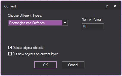
To convert a rectangle into surfaces
- Select the rectangle that you want to convert.
- From the menu,
choose and then click
Result: The rectangle is converted into surfaces.
To convert a spline into pipes
- Select the spline you want to convert.
- From the menu,
choose and then choose .
- Type the number of desired converted pipes on
the dialog box that appears.
- Click OK.
Result: The
spline is converted into the specified number of pipes and automatically
grouped.
To convert using the Specify dialog
- Select the object you want to convert.
- From the menu,
choose and then choose .
Result: The Convert dialog
box opens.
- Select the desired convert type from the available
options. If you do not want to convert the circle into either an arc
or a surface, select Don’t convert.
Note: For circles, select Arcs or
Surfaces and type the number of points,
as discussed above.
- If you want the original object to be replaced
with the new “converted” one, select Delete original
objects.
- If you want the new “converted” objects to be
placed on the current layer, as opposed to the selected object’s original
layer, if different, select Put new objects on
current layer.
- Click OK.
Dividing objects into equal
parts
The command
separates objects into equal parts. The initial object is left intact
(if not deleted) and the parts are identified by newly created objects
such as points or lines.
To divide an arc into lines
- Select the arc you want to divide.
- From the menu,
choose and then click .
- Type the number of lines desired on the dialog
box that appears.
- Click OK.
Result: The arc is divided into equal parts by the
number of lines specified. The lines are automatically drawn from the
center of the arc outward. The result is similar to a pie chart.
To divide an arc into points
- Select the arc you want to divide.
- From the menu,
choose Divide and then click .
- Type the number of points desired on the dialog
box that appears
- Click OK.
Result: The arc is divided into equal parts by the
number of points specified. The points are placed along the arc at the
calculated interval.
To divide a circle into
lines
- Select the circle you want to divide.
- From the menu,
choose and then click .
- Type the number of lines desired on the dialog
box that appears.
- Click OK.
Result: The circle is divided into equal parts by
the number of lines specified. The lines are automatically drawn from
the center of the circle outward. The result is similar to a pie chart.
To divide a circle into
points
- Select the circle you want to divide.
- From the menu,
choose and then click .
- Type the number of points desired on the dialog
box that appears.
- Click OK.
Result: The circle is divided into equal parts by
the number of points specified. The points are placed along the circle
at the calculated interval.
To divide a cylinder
into circles
- Select the cylinder you want to divide.
- From the menu,
choose and then click .
- Type the number of circles desired on the dialog
box that appears.
- Click OK.
Result: The cylinder is divided into equal parts by
the number of circles specified. The circles are stacked within the cylinder
at the calculated interval.
To divide a cylinder
into lines
- Select the cylinder you want to divi
-
and then click .
- Type the number of lines desired on the dialog
box that appears.
- Click OK.
Result: The cylinder is divided into equal parts by
the number of lines specified. The lines follow the same pattern as the
cylinder’s existing segments but at the calculated interval.
To divide a line into points
- Select the line you want to divide.
- From the menu,
choose and then click .
- Type the number of points desired on the dialog
box that appears.
- Click OK.
Result: The line is divided into equal parts by the
number of points specified. The points are placed along the line at the
calculated interval.
You can also divide lines by adding vertices.
In this case no new objects are created; the line is simply divided by
marker points.
To
add a vertex to a line
- Select the line to be divided.
- Right-click on the line segment you want to divide
and choose .
Result: The original line remains intact. A marker
point is placed at the midpoint of the line.
Note: You can repeat this procedure for vertices
within a line. The marker points are always be placed at the midpoint
of the vertices.
- You can drag marker points to re-shape the line.
- If you delete the line, the marker points are
also deleted.
Tip: Alternatively, to perform a divide command,
you can use the Divide tool on the Modify toolbar. This is the same as choosing
from the
sub-menu.
 The Divide button.
To divide using the Specify dialog
- Select the object you want to divide.
- From the menu, choose
and then click .
Result: The Divide dialog
box opens.
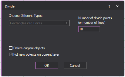
- Check the desired divide type from the available
options.
- To delete the original object when the new ones
are created, select Delete original objects.
- To place the new objects on the current layer,
as opposed to the selected object’s original layer, if different,
select Put new objects on current layer.
- Click OK.
Transforming
objects into surfaces or 3D surfaces
The command
allows you to turn a 2D object like a line or an arc into a surface, or
turn a surface into a 3D surface or 3D solid.
To 3D Transform a line
- Select the line you want to 3D Transform.
- From the menu,
choose and then click
.
- Type the distance to 3D Transform the line on
the dialog box that appears. The transformation occurs parallel to
the axis of the Height value in Plan view. For example, a line shown
in plan view transforms vertically. For splines, you must specify
the number of segments for the new surface in the #
of Points box.
- Click OK.
Result: The
line is transformed into a surface based on your specified distance.
To 3D Transform an arc
- Select the arc you want to 3D Transform.
- From the menu,
choose and then click
.
- Type the distance to 3D Transform the line on
the dialog box that appears. The transformation occurs parallel to
the axis of the Height value in Plan view. For example, an arc shown
in plan view transforms vertically.
- Type the number of segments for the new surface.
The number entered cannot be 1. The higher the number the more circular
the surface will be.
- Click OK.
Result: The
arc is transformed into surfaces based on your specified number of segments
and distance.
To 3D Transform a surface into a solid
- Select the surface you want to 3D Transform.
- From the menu,
choose and then click
.
- Type the distance to transform the surface on
the dialog box that appears. The transformation occurs parallel to
the axis of the Height value in Plan view. For example, a surface
shown in plan view transforms vertically.
Tip: You can also use the 3D
Transform tool on the Modify toolbar.
 The 3D Transform button.
- Click OK.
Result: The
surface is transformed into a solid based on your specified distance.
Transforming objects into
transformed objects
The command
allows you to turn a 2D object like a line or an arc into a transformed
object where transformed surface geometry can be modified with options
that apply textures to fit the geometry and a smoother appearance.
The transformation will occur parallel
to the axis of the missing coordinate. Objects such as line, spline, arc,
circle or rectangle shown in plan view will transform vertically.
To transform an arc into a transformed object
- Select the arc that you want to transform.
- From the menu,
choose and then click
.
Result: The Transform Arcs into
Transformed Objects window appears.
- Type the value for Distance
1 to set the transform distance of one end of the arc.
- Type the value for Distance
2 to set the transform distance of the opposite end of
the arc.
Note: If you wish to have a uniform height for the
transformed object, set the same value for Distance
1 and Distance 2.
- Type the Number of Points to
set the number of vertices that divide the arc. You cannot type the
number 1. The higher the number, the smoother the curve of the transformed
object.
- Type the number of Transformed
Segments to specify the number of dividing segments that
will make the transformed object.
- Select the Transform in Both
Directions checkbox if you wish to transform the 2D object
in both opposite directions from the axis with respect to the Wireframe
view currently viewing the object.
- Select the Stretch Texture checkbox if you wish to
fit the applied image or video texture onto the resulting transformed
object geometry. If disabled, the default rectangular texture is applied
to the largest extents of the object, and sections will be cut based
on the resulting height (if two transform distances were used).
- Select the Smooth Shading checkbox
if you wish to display transformed objects with a smoother appearance.
- Click OK.
To transform a line into a transformed object
- Select the line that you want to transform.
- From the menu,
choose and then click
Lines into Transformed Objects.
Result: The Transform Splines
into Transformed Objects window
appears.
- Type the value for Distance
1 to set the transform distance of one end of the line.
- Type the value for Distance
2 to set the transform distance of the opposite end of
the line.
Note: If you wish to have a uniform height for the
transformed object, set the same value for Distance
1 and Distance 2.
- Type the Number of Points to
set the transformed distance of the opposite end of the line.
- Type the number of Transformed Segments to specify the number
of dividing segments that will make the transformed object.
- Select the Transform in Both
Directions checkbox if you wish to transform the 2D object
in both opposite directions from the axis with respect to the Wireframe
view currently viewing the object.
- Select the Stretch Texture checkbox if you wish to fit the applied
image or video texture onto the resulting transformed object geometry.
if disabled, the default rectangular texture is applied to the largest
extents of the object, and sections will be cut based on the resulting
height (if two transform distances were used).
- Select the Smooth Shading checkbox
if you wish to display transform objects with a smoother appearance.
- Click OK.
To transform a circle into a transformed object
- Select the circle that you want to transform.
- From the menu,
choose and then click
.
Result: The Transform Circles
into Transformed Objects window
appears.
- Type the value for Distance
1 to set the transform distance of one end of the circle.
- Type the value for Distance
2 to set the transform distance of the opposite end of
the circle.
Note: If you wish to have a uniform height for the
transformed object, set the same value for Distance
1 and Distance 2.
- Type the Number of Points to set the number of vertices that divide
the circle. You cannot type the number 1. The higher the number, the
smoother the curve of the transformed object.
- Type the number of Transformed
Segments to specify the number of dividing segments that
will make the transformed object.
- Select the Transform in Both
Directions checkbox if you wish to transform the 2D object
in both opposite directions from the axis with respect to the Wireframe
view currently viewing the object.
- Select the Stretch Texture checkbox
if you wish to fit the applied image or video texture onto the resulting
transformed object geometry. If disabled, the default rectangular
texture is applied to the largest extents of the object, and sections
will be cut based on the resulting height (if two transform distances
were used).
- Select the Smooth Shading checkbox
if you wish to display transformed objects with a smoother appearance.
- Click OK.
To transform a rectangle into a transformed object
- Select the rectangle that you want to transform.
- From the menu,
choose and then click
.
Result: The window appears.
- Type the value for Distance
1 to set the transform distance of one end of the rectangle.
- Type the value for Distance
2 to set the transform distance of the opposite end of
the rectangle.
Note: If you wish to have a uniform height for the
transformed object, set the same value for Distance
1 and Distance 2.
- Type the number of Transformed
Segments to specify the number of dividing segments that
will make the transformed object.
- Select the Transform in Both
Directions checkbox if you wish to transform the 2D object
in both opposite directions from the axis with respect to the Wireframe
view currently viewing the object.
- Select the Stretch Texture checkbox
if you wish to fit the applied image or video texture onto the resulting
transformed object geometry. If disabled, the default rectangular
texture is applied to the largest extents of the object, and sections
will be cut based on the resulting height (if two transform distances
were used).
- Select the Smooth Shading checkbox
if you wish to display transformed objects with a smoother appearance.
- Click OK.
Note: You can also view and edit the transformed
objects properties in the transformed object’s Properties
tab.
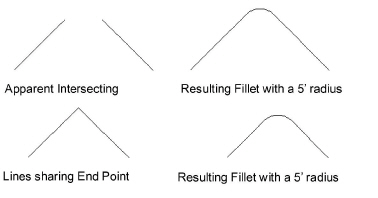
Filleting lines
The command
joins two lines sharing the same end point or two apparent intersecting
lines with an arc. A fillet radius must be specified to achieve the desired
fillet angle.
To set the fillet radius
- From the menu,
choose and then click .
- Type a radius measurement for the resulting fillet.
Note: All subsequent fillet commands follow this
value until it is modified again.
To fillet two lines
- Select the lines to be filleted.
- From the menu,
choose , then click .
Result: The lines are joined by an arc based on the
value set for the fillet radius.
Notes:
- You must set a fillet radius to perform this
command.
- If the fillet radius is 0, the lines are extended
and joined at their intersection. If they are already intersecting,
nothing occurs.
Aligning objects
You can use the Align tools
to quickly and precisely align a series of selected objects in your drawing.
For example, if you have manually placed some chairs in your drawing,
you can select them all and align them in one of six ways.
You can align the selected objects from
the:
- top
- bottom
- left
- right
- center (horizontally)
- center (vertically)
The following procedures illustrate each
of these align methods when applied to four sofas placed manually in your
drawing, as shown
in the following graphic:
To align objects from the top
- Select the objects that you want to align by clicking
and dragging a selection box around them. In this example, you would
select the four sofas shown in the graphic.
- From the menu,
choose and then click .
The top edges of the selected objects are aligned.
Note: Before you align the objects, you must ensure
that they will not overlap each other in their new positions.
To align objects from the bottom
- Select the objects that you want to align by clicking
and dragging a selection box around them. In this example, you would
select the four sofas shown in the first graphic.
- From the menu,
choose and then click .
The bottom edges of the selected objects are aligned.
Note: Before you align the objects, you must ensure
that they will not overlap each other in their new positions.
To align objects from the left side
- Select the objects that you want to align by clicking
and dragging a selection box around them. In this example, you would
select the four sofas shown in the first graphic.
- From the menu,
choose and then click .
The left edges of the selected objects are aligned.
Note: Before you align the objects, you must ensure
that they will not overlap each other in their new positions. In the following
graphic, for example, the top two sofas overlap because of their original
position.
To align objects from the right side
- Select the objects that you want to align by clicking
and dragging a selection box around them. In this example, you would
select the four sofas shown in the first graphic.
- From the menu,
choose . The right edges of the
selected objects are aligned.
Note: Before you align the objects, you must ensure
that they will not overlap each other in their new positions. In the following
graphic, for example, the top two sofas overlap because of their original
position.
To align the center points of objects
horizontally
- Select the objects that you want to align by clicking
and dragging a selection box around them. In this example, you would
select the four sofas shown in the first graphic.
- From the menu,
choose . The center
points of the selected objects are aligned horizontally.
Note: Before you align the objects, you must ensure
that they will not overlap each other in their new positions. In the following
graphic, for example, the top two sofas overlap because of their original
position.
To align the center points of objects
vertically
- Select the objects that you want to align by clicking
and dragging a selection box around them. In this example, you would
select the four sofas shown in the first graphic.
- From the menu,
choose . The center
points of the selected objects are aligned vertically.
Note: Before you align the objects, you must ensure
that they will not overlap each other in their new positions.
Boolean
operations
Note: This feature is recommended for advanced users
only.
The Boolean Operations series of tools
enable you to choose two different sets of objects and then perform one
of three actions on them:

|
Unite
Objects: This option enables you to join the two sets of
objects together as one, merging their common area so that it
is indistinguishable from the original objects. |

|
Intersect
Objects: This option enables you to choose two sets of
intersecting objects and then delete everything outside of their
common area. |

|
Subtract
Objects: This option enables you to select two sets of
objects, and then subtract the overlapping area of the second
set from the first set that you chose. |
Selection sets
When using any of the Boolean Operations
tools, you must select two sets of objects, Set
1 and Set 2. Here
are some guidelines for your selection sets:
- The only valid 2D object for Boolean operations
is a surface.
- Valid 3D objects for Boolean operations include:
Risers, Cylinders, Spheres, Cones, Extruded Surfaces, as well as any
3D objects resulting from a 3D x 3D Boolean operation. You cannot
perform Boolean operations on library items or venues. To include
a venue, you must first break it into surfaces.
- Each selection set include only one 2D object
or only one 3D object.
- You cannot combine 2D and 3D objects in a single
selection set.
- Each set can include either 2D or 3D objects.
You can specify a selection set comprising one or more 2D objects
and a selection set with one 3D object in the same Boolean operation.
- All operations that involve a 3D object require
that Set 1 intersects with Set 2.
- For operations that involve only 2D objects, the
objects in each selection set do not need to intersect physically;
however, the projection of the objects in Set 2 must intersect with
those in Set 1 along the plane in which you are currently working.
For details, see “Projection
and intersection”.
- In a Boolean operation involving one or more 2D
objects in one selection set and a 3D object in the other selection
set, the 3D object must be in the second selection set.
With these rules in mind, the possibilities
for selection set combinations are:
- one 3d object x one 3d object
- one 2d object x one 2d object
- one 2d object x one 3d object
Color and texture
- Based on the type of object in your selection
set, color and texture are treated differently after you perform a
Boolean operation.
- 2D objects maintain their color and texture after
a Boolean operation is performed on them; 3D objects maintain only
their color (they lose any texture applied to them).
- In a Boolean operation involving only 2D objects
or only 3D objects, the objects in the second selection set adopt
the properties of the objects in the first selection set after the
operation is complete.
- In a Boolean operation involving only 3D objects,
if one or both of the objects has a texture applied, then both objects
end up with no texture or color after the operation is complete.
- When you perform a Boolean operation on a 3D object,
the object is converted into a solid after the operation. Since you
cannot apply a texture to solids, it is recommended that you convert
it into a custom library object and then apply the texture. For details,
see “To
create a custom library item”. Alternately, you can convert
the object into 2D surfaces before you perform the Boolean operation
and then customize it.
Projection and intersection
When performing any of the Boolean Operations
procedures on selection sets involving 2D and 3D objects, note the difference
between projection and intersection.
- Projection:
When you are working with only 2D objects, the objects in one selection
set need only “project” upon the objects in the other set within the
active view; that is, the objects in each set do not have to physically
touch, but they must overlap in the view in which you are performing
the action.
- Intersection:
When you are working with only 3D objects or a mixture of 2D and 3D
objects, the objects in each selection set must physically touch before
you can successfully perform the Boolean Operations action, that is,
they must intersect with each other.
About the Boolean Operations feature and View Planes
There are three View Planes or axial planes
in your drawing: (XY-plane, XZ-plane, and YZ-plane). Based on the view
you are in (Plan, Front, Back, Left, or Right), some of these planes may
not be visible. For example, when you are in Plan view, the XZ and YZ
planes are invisible.
When you perform any of the Boolean Operations
procedures with 2D surfaces in the second selection set, note how the
objects appear on the active View Plane. Their appearance will give you
an idea of the What-You-See-Is-What-You-Get result from the perspective
of the active view. By noting the active View Planes, you can perform
any of the Boolean operations on surfaces without requiring them to be
co-planar.
Examples - 2D parallel objects
In the following graphic, selection set
1 includes a red 2D surface, and selection set 2 includes a yellow 2D
surface. Both surfaces were drawn so that they overlap in Plan View, as
shown in the upper-left quadrant:
When you perform a Unite procedure with
these sets in the Plan view quadrant, the results are successful because
you can see that the yellow surface projects onto the red surface in this
view (they overlap).
However, when you try to do the same action
in the bottom left quadrant (Front View), the operation is unsuccessful
because neither surface projects onto the other (they do not overlap in
this view).
Tip:
To overcome this limitation, in the case
noted above, you could extrude the surface in selection set 2 into a 3D
solid, ensuring that the solid touches the surface in selection set 1.
In some cases, it is much easier to perform a Boolean operation with 2D
surfaces in the first selection set and a 3D solid in the second set because
the operation is View Plane independent. For example, when you are cutting
windows in walls, it is usually best to use 2D surfaces for both the windows
and walls because you can project the image of the windows onto the walls
(for details, see “To
cut holes in walls with the Subtract tool”). However, if you
have an odd-shaped building like a Pentagon, it would be impossible to
align the walls with the View Plane. In this case, therefore, it would
be easier to use cylinders for the shape of the windows and intersect
them with the walls wherever you want a window to appear, before performing
the Subtract procedure.
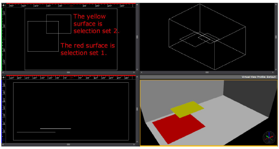
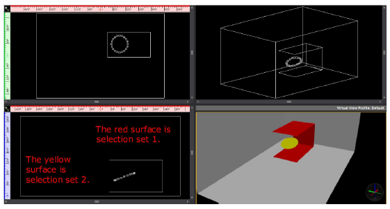
Examples - 2D non-parallel objects
If the surfaces in each of the selection
sets are not parallel, the results of a Boolean operation can differ according
to the active View Plane. In the following graphic, the red surfaces comprise
selection set 1 and the yellow surface is selection set 2. Note that the
yellow surface is rotated so that it is not parallel to any of the surfaces
in set 1.
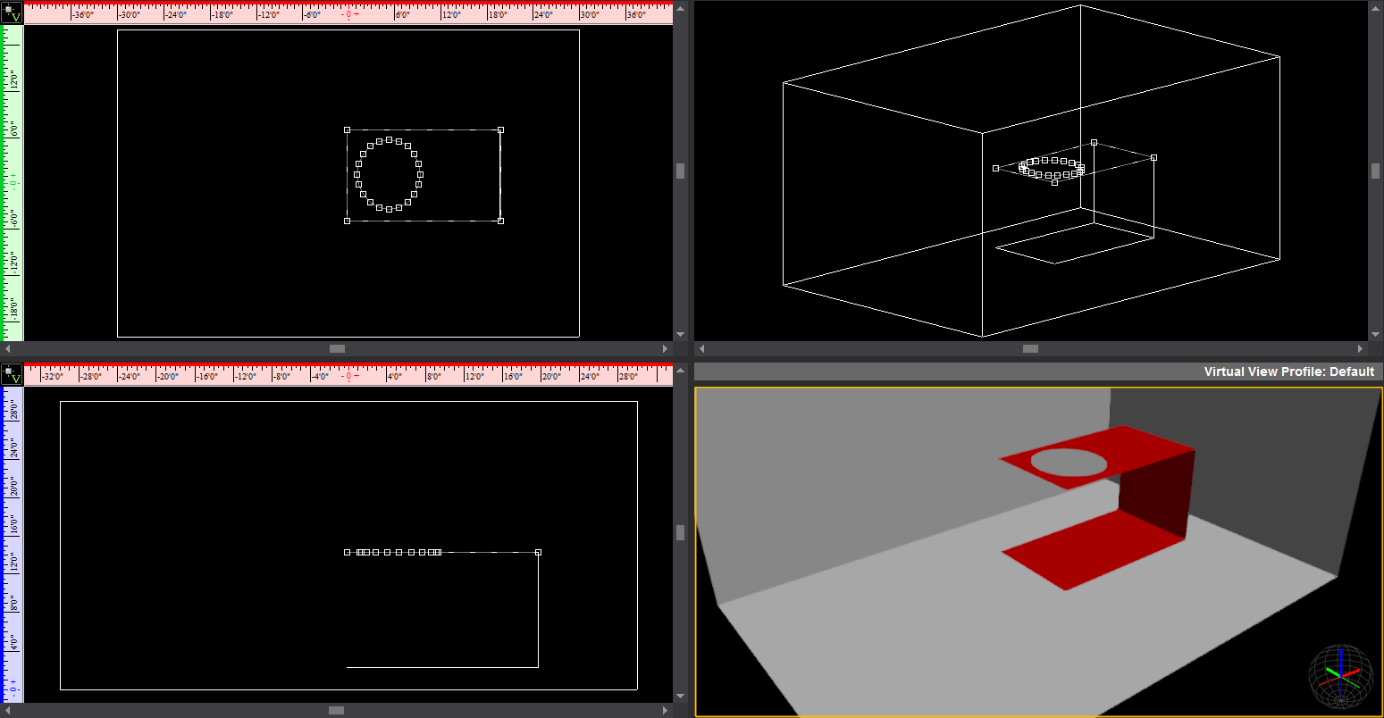
In this case, when you perform a Subtract
operation in Plan view, the results are predictable: a hole the size of
the yellow surface appears on the selected red surface, as shown below.
Note that the hole is not perfectly circular, but rather take on the exact
shape of the angled circle as it appears in Plan view.
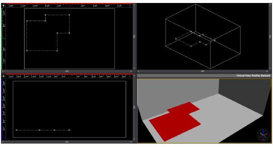
When you perform the same action in Front
view, the operation fails because none of the surfaces in set 1 or set
2 is co-planar in this view.
However, when you switch to Right view
and perform a Subtract, a hole appears only on the back surface (the one
onto which the circle projects in this view), as shown below.
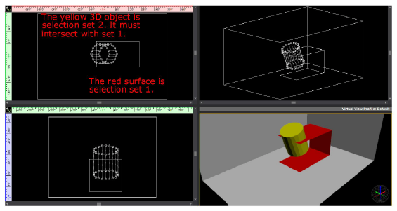
Example - 2D object and 3D solid
Note that if you convert the circular surface
into a 3D solid, then you must ensure that it physically intersects with
at least one of the 2D surfaces in set 1 before you can successfully perform
a Boolean Operations procedure, as shown below; it is not enough for the
object to project upon one of the surfaces. For details on projection
and intersection, see “Projection
and intersection”.
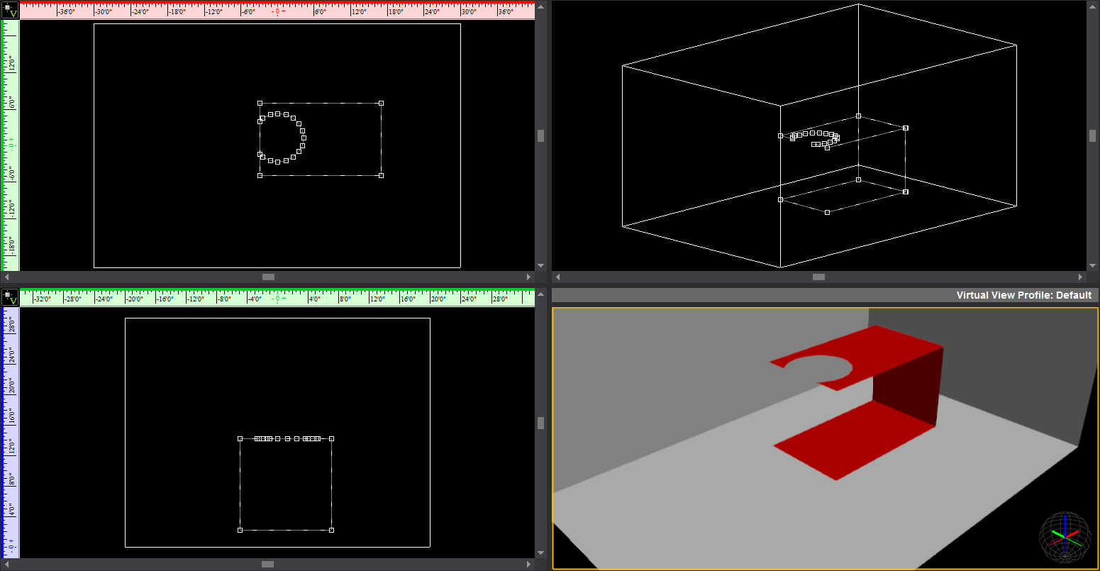
When you perform a Subtract action on these
sets in Plan view, the results are as follows:
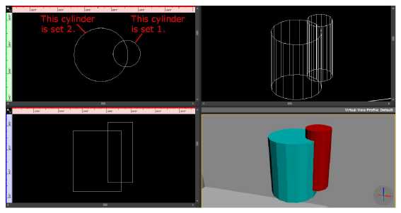
Examples of each Boolean Operations procedure
The following graphic shows the two object
sets that will be used as examples in each of the procedures in this section.
Set 1 consists of the red cylinder and
set 2 consists of the aqua cylinder:
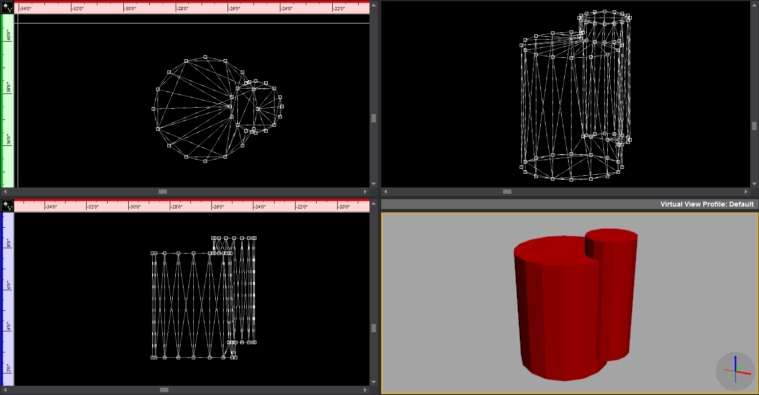
Uniting objects
This option enables you to join two sets
of intersecting objects together as one, merging their common area. Note
that when you unite objects, the second set of objects adopts the properties
of the first set that you chose (i.e., its color, texture, and so on).
Note: If you are uniting a 2D object like a surface
with a 3D object like a riser, the 2D object must be in the first selection
set and the 3D object in the second. After you perform this operation,
the 3D object adopts the properties of the 2D object, becoming a flat
surface with the same color and texture as the 2D object.
The following graphic shows how the two
sets of objects are united to become one object. Note how the second object
set (the aqua cylinder) takes on the properties of set 1, becoming red.
Note: When you perform a Boolean operation on a
3D object, the object is converted into a solid after the operation. Since
you cannot apply a texture to solids, it is recommended that you convert
it into a custom library object and then apply the texture. For details,
see “To
create a custom library item”. Alternately, you can convert
the object into 2D surfaces before you perform the Boolean operation and
then customize it.
To unite objects with the Boolean Operations feature
Note that you can only select one 2D object
in each selection set; you cannot select multiple 3D objects in a selection
set.
- In one of the 2D wireframe views, select the first
object or objects that you want to join with the second object or
objects.
- From the .
- Click to select the second object set that you
want to join with first set.
- Right-click and choose .
Result: Based on the complexity of your selections,
you may have to wait a few moments for the calculations to finish and
the objects to be united.
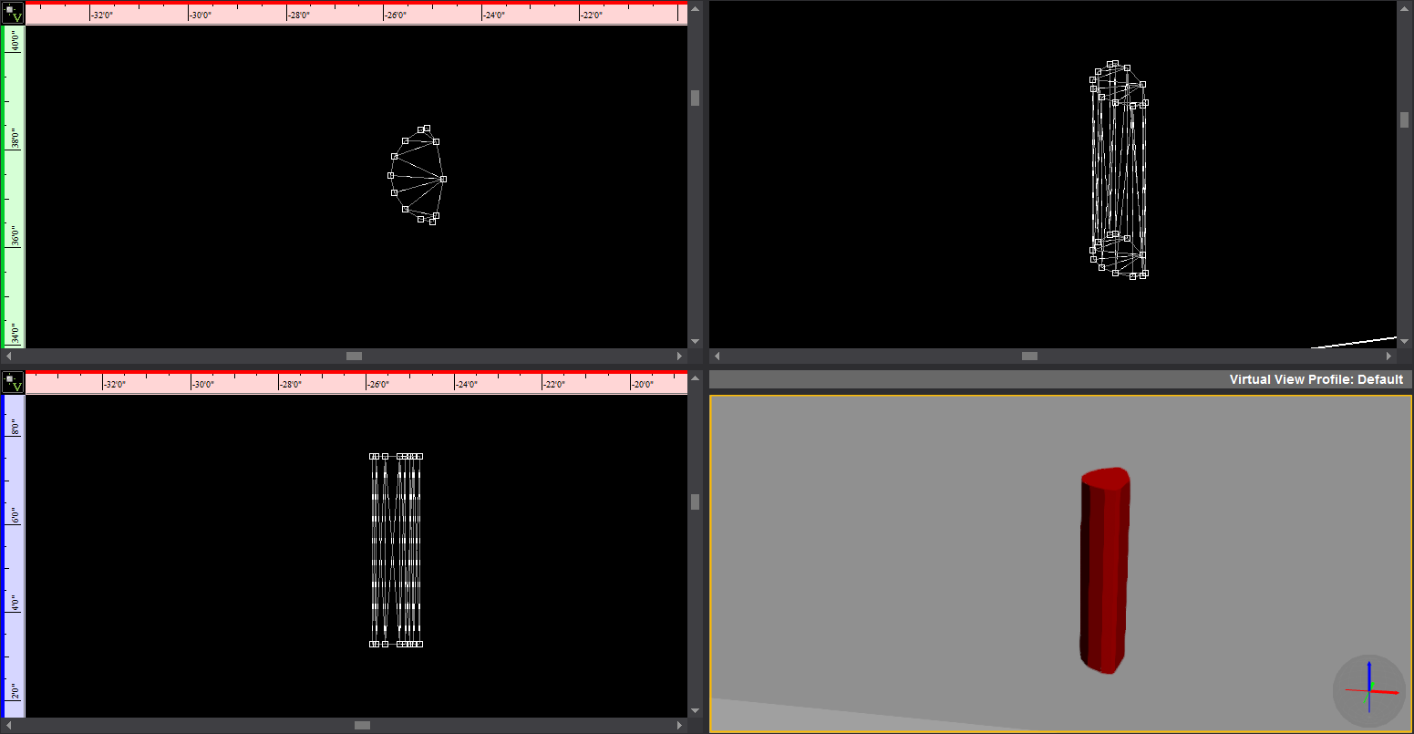
Intersecting objects
This option enables you to choose two sets
of overlapping or intersecting objects and then delete everything outside
of their common area. Note that when you intersect objects, the intersection
that remains behind maintains the properties of the objects in the first
selection set.
The following graphic shows the result
of intersecting the red and aqua cylinders. Note how the remaining portion
is red, just like the cylinder in set 1.
To intersect objects with the Boolean Operations feature
Note that you can only select one 2D object
in each selection set; you cannot select multiple 3D objects in a selection
set.
- In one of the 2D wireframe views, select the first
object or objects that you want to intersect with the second object
or objects.
- From the .
- Click to select the second object set that you
want to intersect with first set.
- Right-click and choose .
Result: Based on the complexity of your selections,
you may have to wait a few moments for the calculations to finish and
the objects to be intersected.
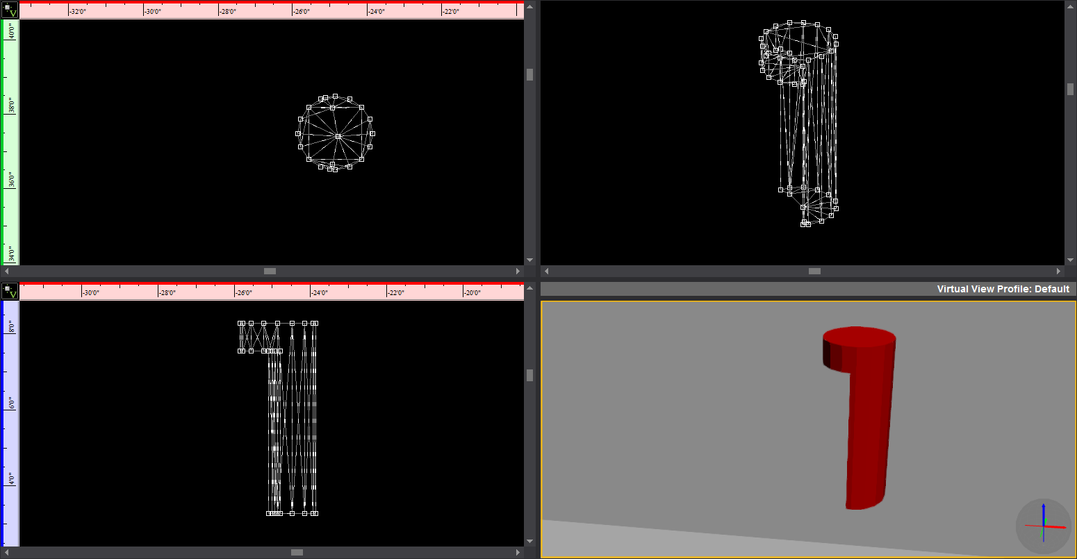
Subtracting
objects
This option enables you to select two sets
of objects, and then subtract the overlapping area of the second set from
the first set that you chose.
This feature is particularly useful for
cutting a hole in a surface to create a window. Note, however, that if
you are cutting a hole in a wall to create a window, it is easiest to
work only with 2D objects in each selection set since they do not have
to physically touch. Instead, the “window” shapes need only to project
onto the walls in the active view. For details, see “Projection and intersection”. For
details on cutting holes into walls, see “To cut holes in walls with the Subtract tool”.
The following graphic shows the result
of subtracting the aqua cylinder from the red cylinder.
To subtract objects with the Boolean Operations feature
Note that you can only select one 2D object
in each selection set; you cannot select multiple 3D objects in a selection
set.
- In the Drawing Wireframe tab, select the first
object that you want to keep in your drawing (the second set of objects
will be subtracted from this set).
- From the .
- Click to select the second object set that you
want to subtract from the first set.
- Right-click and choose .
Result: Based on the complexity of your selections,
you may have to wait a few moments for the calculations to finish and
the objects to be subtracted.
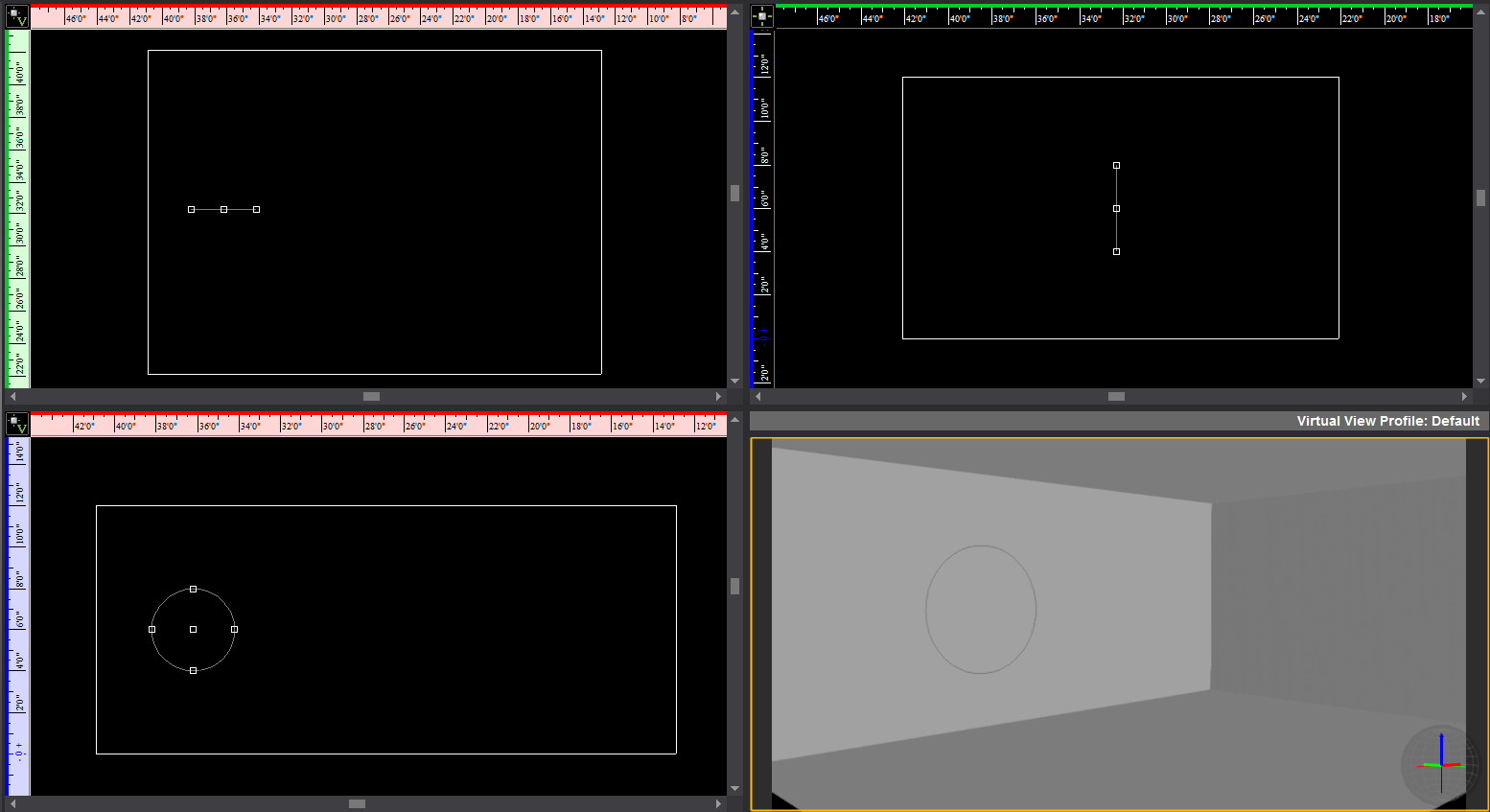
To cut holes in
walls with the Subtract tool
In this procedure, you use the Boolean
Operations > Subtract tool to cut a line of round windows into a wall
of your venue.
- In the Drawing Quad
tab, draw a venue (for example, a room).
- Click the venue to select it, and then right-click
and choose >>.
Note: Since the window shapes are a series of 2D
surfaces, it is best to convert the 3D venue into a 2D surface as well.
This way, the window shapes only have to project onto the “walls” in the
same plane. If the venue is a 3D object, then the windows would have to
physically touch them (intersect) before you perform the Subtract operation.
For details, see “Projection
and intersection”.
- Click to highlight the Front view quadrant.
- Click the Circle tool,
and then click OK to accept the default
size of 4’.
- In the Front view quadrant, click to place the
circle half-way up the wall, at one end of the room, as shown below:
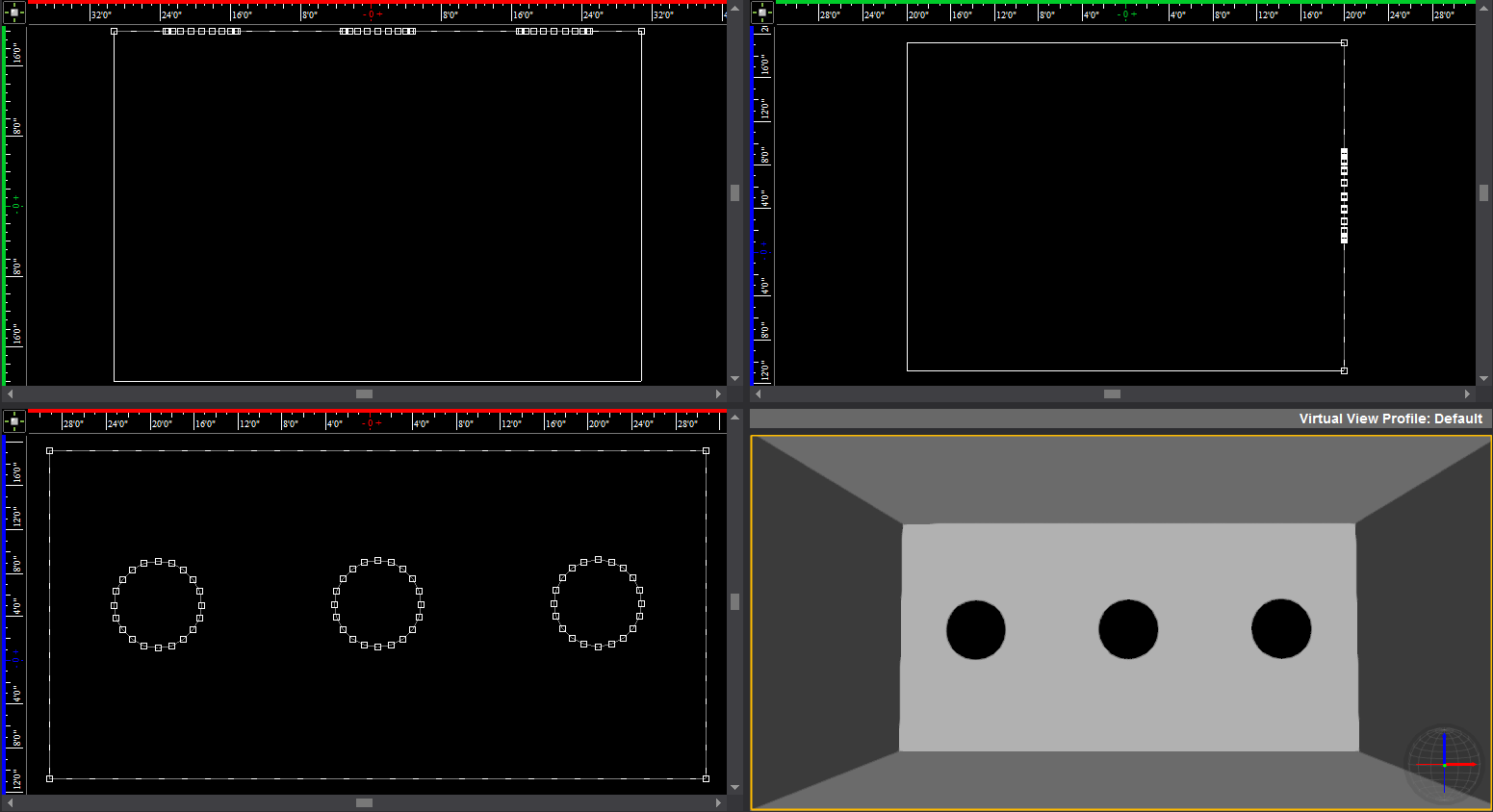
- With the circle still selected, right-click and
choose >>.
- Type 20 and click OK.
(The higher the number of points, the smoother the outline of the
circle.)
- With the circle still selected, click >
> .
- In the Front view quadrant, click the extreme
right-hand wall to pick the destination point.
- Type 3 for the Number in row and 20 for the Interval,
and then click OK.
Result: The circular surfaces are arrayed along the
length of the room.
- In the Plan view quadrant, click the wall outline
to select it, and then click >>.
- Click a circular surface, and then right-click
and select .
- Repeat step 11
and 12 for the next circular
surface.
Result: The circular windows are “cut” into the wall
of the venue, as shown in the following graphic:
Consolidate
Mesh
This feature helps increase performance
in Virtual Views by enabling you to consolidate complex objects comprising
multiple polygons/”sub-objects” into objects that behave as a single entity.
Consolidating meshes is essentially the same as creating new (custom)
Library Items. However, while both methods make Vivien “see” the object
as a single entity, when you use the
command, you don’t actually create a new Library Item, and the amount
of increase in file size depends on the items that are selected.
To determine which objects in your scene
to consolidate, it is recommended that you enable the new Object
Bounding Box feature on the View Options
tab. Once you do so, objects that appear with a high number of bounding
boxes are all candidates for consolidation.
Notes:
- It is not recommended to include library items
from the WYSIWYG/Vivien library as part of the selection which mesh
consolidation will be performed on.
- If you consolidate an object to which a texture
has been applied, the texture may not behave correctly because the
object’s underlying geometry will be different. To maintain proper
texturing AND have the file perform well for pre-visualization, it
is recommended that you create a copy of the final file. Optimize
the copy, and then use the optimized file for pre-programming purposes
and the original file for screenshots and/or renderings.
To use the Consolidate Mesh feature
Note: Boolean Operations cannot be performed on
objects that have been Consolidated.
- In a wireframe view, select the object that you
want to consolidate.
- From
the .
Result: A dialog box appears, asking for Mesh Consolidation
to continue for all other objects and skip the Library objects.

- Click Yes to
proceed with the operation and excluding the Library objects.
Result: A dialog box appears, confirming that the
operation is complete, and displaying the number of polygons that have
been removed from the file.
- Click OK. The item
is now consolidated into an abject that behaves as a single entity.
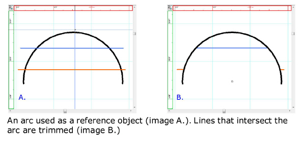
Trimming lines
The Trim tool
can be used to remove sections of drawn lines that intersect a referenced
object (arc, circle or line) drawn on the same plane. Trimming will remove
all of the selected line segment, stopping at where it intersects with
the referenced object.
To trim a line
- In the drawing wireframe, select the reference
object.
- From the menu,
choose
 The Trim button.
Tip: The keyboard shortcut to access the Trim tool
is CTRL+T.
- Click on a segment of line you want to remove
that intersects the referenced object.
Result: The selected line segment will be removed,
from where the line intersects the reference object to where the line
ends or intersects the object again.
- Continue trimming lines as needed.
- To end trimming line, right-click and choose or .
Alternately, the ESC key can be pressed.
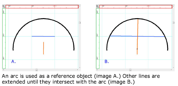
Extending lines
The Extend tool can be used to lengthen straight lines
until they touch a referenced object (arc, circle or line) drawn on the
same plane.
Note: Lines can only be extended if they are able
to intersect the reference object when extended. If they will not intersect,
the line will not extend.
To extend a line
- In the drawing, select the reference object (line,
arc or circle).
- From the menu,
choose .
 The Extendbutton.
Tip: The keyboard shortcut to access the extend
tool is CTRL+SHIFT+T.
- Click on a line that you want to extend to the
reference object.
Result: If the selected line can intersect the reference
object, it will extend until it has done so. If the line can not intersect
the object, it does not extend. The selected line will intersect all other
objects in its path to reach the reference object. If the line can intersect
the reference object on both ends, both line ends will extend until they
intersect the reference object.
- Continue extending lines as needed.
- To end extending lines, right-click and choose
or . Alternately, the ESC key
can be pressed.