Drawing
objects
You draw
objects in drawing wireframe views (the Drawing Wireframe tab
and additionally, in Vivien Virtual Event Designer,
the Drawing Quad tab). The menu lists the objects that you can draw.
Keep the following tips in mind when you
are drawing objects:
Drawing tips
- At any time, instead of clicking points with
the mouse, you can type in the desired coordinates. See “Command line”.
- Create shortcuts for library objects. See “Shortcut
bars”.
- Use the Height value in Vivien Virtual Event Designer.
“The
Height value”.
- Use keyboard shortcuts and hot keys. See “About keyboard shortcuts and hotkeys”.
- Before you place a 2D/3D primitive object, screen,
or LED wall into your drawing, you can right-click on the object and
select its Insertion Point from the menu that appears. See “Insertion points” for
details.
Drawing
points
Points identify specific coordinates in
3D space. You can insert points as references or as scenic elements. There
are four different point styles: dot, cross, square, and circle. The default
point style is defined for the document.
To draw a point
- From the menu,
choose .
or
Click the Point tool
on the Draw toolbar.
 The Point button.
- Click on the drawing to place the point.
For information on modifying a point once
you have drawn it, see “Point
tab”.
Drawing lines
Lines are 2D objects that join vertices.
In Vivien, you can draw lines continuously, which means you can easily
join multiple vertices to create shapes.
Lines come in
four styles:
Line styles determine how line objects
appear on your drawing and can be modified at any time.
Line patterns are available to a Rectangle,
Circle, Ellipse, Arc, and Elliptical Arc.
You can 3D Transform lines into surfaces.
For more on transforming lines, “Transforming
objects into surfaces or 3D surfaces”.
When you draw multi-segmented lines, or
add a line to a surface, or when drawing a room using the Room Builder,
the next point of the line you wish to add snaps automatically to the
previously drawn line/surface’s endpoint, midpoint or intersection when
the Endpoint Snap, Midpoint
Snap, and/or Intersection
Snap are enabled.
To draw a line freehand
- From the menu,
choose .
- From the sub-menu, select ,
, , .
Tip: You can also use the appropriate line tool
on the Draw toolbar. The available line
tools are as follows:
- Click on the wireframe at the starting point of
the line.
- Drag the next vertex to its end point and click.
- Continue to place vertices of the line as needed
on and click.
- Continue to place vertices as needed.
- To end the line at the last vertex you placed,
right-click and choose .
To cancel the drawing of the line, right-click
and choose . This erases the entire
line from the drawing.
To join the last point you placed with
the first one you placed, right-click and choose .
To draw a line by specifying coordinates
You can also draw lines using coordinates
by specifying absolute or relative values.
- From the menu,
click and choose ,
, or .
- In the Command Line,
type the absolute X, Y and Z coordinates (separated by commas) where
you want the line to start (i.e. @0,0,0).
- Press ENTER to establish
the first point of the line.
- In the Command Line,
type the absolute X, Y, and Z coordinates where you want the next
point of the line or,
Using the relative values, in the Command Line, type @,
followed by the length towards the next point of the line (positive or
negative direction), (i.e. @3’6”,0,3’).
- Press ENTER to draw
the new line segment.
- Continue to type absolute or relative values and
press ENTER to draw the next line
segments.
- When you are finished drawing the lines, right-click
and click .
To draw a line by specifying its length and angle
- From the menu,
click and
choose , ,
or
.
- In the Command Line,
type the X, Y, and Z coordinates (separated by commas) where you want
the line to start (i.e. @
0,0,0).
- Press ENTER to establish
the first point of the line.
- In the Command Line,
type the length towards the next point of the line followed by the
< sign and the angle (direction),
(i.e. @3’6”<-180).
- Press ENTER to draw
the new line segment.
- Continue to type the length and angle in the Command Line.
- When you are finished drawing the lines, right-click
and click .
Tip: You can also determine the direction of the
line from the cursor’s current position relative to the start point set
in step 2.
For information on modifying a line once
you have drawn it, see “Line
tab”.
Drawing splines
Splines are curved lines that pass through
multiple vertices that influence the shape of the curve (or french curve).
To draw a Spline
- From the menu,
choose .
Tip: You can also use the appropriate spline tool
on the Draw toolbar.
 The Spline button.
- Click on the drawing at the starting point of
the spline.
- Drag the next vertex to its end point and click.
- Continue to place vertices of the spline as needed
and click.
- Continue to place vertices as needed.
- To end the line at the last vertex you placed,
right-click and choose .
Right-click and choose to cancel the drawing and erase the entire spline.
Drawing
circles
There are two ways to draw circles:
- Specify the horizontal and vertical radius and
place the circle in the drawing.
- Draw the circle freehand.
To draw a circle
- From the menu,
choose .
or
Click the Circle tool
on the Draw toolbar.
 The Circle button.
Result: The New Circle
dialog box opens.
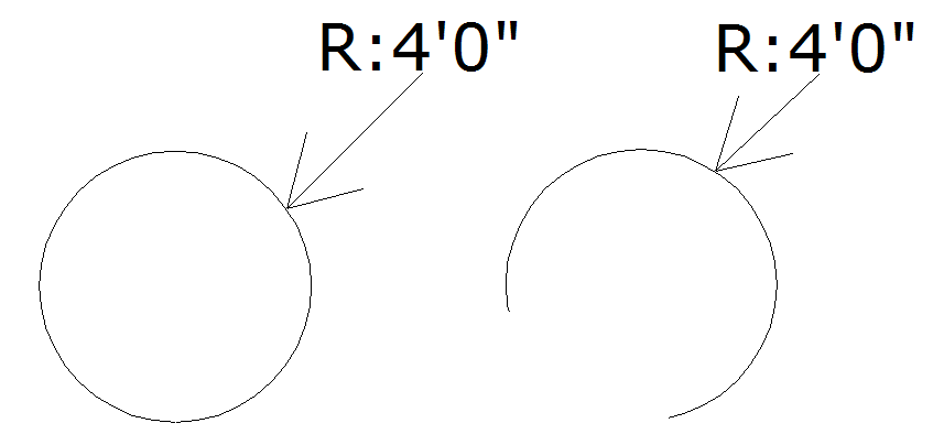
- In the Horizontal Radius box,
type the horizontal radius for the circle. The default value is 4’0”.
- In the Vertical Radius box,
type the vertical radius for the circle. The default value is 4’0”.
Note: When the Horizontal and Vertical radii are
the same, a circular object is created; when they are different, the object
is oval-shaped.
- To ensure that the circle remains proportionately
the same when resized, leave the Lock Ratio checkbox
selected. If you clear this checkbox, then you can manually resize
the circle in any direction, regardless of its original measurements.
- Click OK.
- Click in the drawing to place the circle.
To draw a circle in Freehand mode
- Switch to Freehand mode, if you are not already
in it, by clicking the Freehand Mode tool
on the Tools toolbar.
 The Freehand
Mode button.
The Freehand
Mode button.
- From the menu,
choose .
or
Click the Circle tool
on the Draw toolbar.
 The Circle button.
Result: The New Circle
dialog box opens.
- Click to place the center of the circle.
- Click to set the radius for the circle.
Drawing
arcs
There are two ways to draw an arc:
- Specify the arc radius, start and end angles and
place the arc in the drawing.
- Draw the arc freehand.
To draw an arc
- From the menu,
choose .
or
Click the Arc tool
on the Draw toolbar.
 The Arc button.
Result: The New Arc dialog
box opens.
- In the Radius box,
enter a radius for the arc. The default value is 4’0”.
- In the Start Angle
box, enter the start angle. The default value is 0.00.
- In the End Angle box,
enter the end angle for the arc. The default value is 180.00.
- Click OK.
- Click on the drawing to place the arc.
To draw an arc in Freehand mode
- Switch to Freehand Mode,
if you are not already in it, by clicking the Freehand
Mode tool on the Tools toolbar.
 The Freehand
Mode button.
The Freehand
Mode button.
- From the menu,
choose .
or
Click the Arc tool
on the Draw toolbar.
 The Arc button.
- Click to place the start point of the arc.
- Click to place the end point of the arc.
- Click to place the middle point of the arc.
Drawing
elliptical arcs
There are two ways to draw an arc:
- Specify the elliptical arc radius, start and end
angles and place the arc in the drawing.
- Draw the elliptical arc freehand.
To draw an elliptical arc
- From the menu,
choose .
or
Click the Arc Elliptical tool
on the Draw toolbar.
 The Arc
Elliptical button.
The Arc
Elliptical button.
Result: The New Elliptical Arc
dialog box opens.
- In the Radius box,
enter a radius for the elliptical arc. The default value is 4’0”.
- In the Start Angle box,
enter the start elliptical angle. The default value is 0.00.
- In the End Angle box,
enter the end angle for the elliptical arc. The default value is 180.00.
- Click OK.
- Click on the drawing to place the elliptical arc.
- Click and drag the mid point of the arc to create
the desired elliptical.
To draw an elliptical arc in Freehand mode
- Switch to Freehand Mode, if you are
not already in it, by clicking the Freehand Mode tool
on the Tools toolbar.
 The Freehand
Mode button.
The Freehand
Mode button.
- From the menu,
choose .
or
Click the Arc Elliptical tool
on the Draw toolbar.
 The Arc
Elliptical button.
The Arc
Elliptical button.
- Click to place the start point of the elliptical
arc.
- Click to set the horizontal and vertical radii
of the elliptical arc.
- Click to set the start point of the ellipse.
- Click to set the end point of the ellipse.
Drawing
rectangles
There are two ways to draw rectangles:
- Specify the length and width and place the rectangle
in the drawing.
- Draw the rectangle freehand.
To draw a Rectangle
- From the menu,
choose .
or
Click the Rectangle tool
on the Draw toolbar.
 The Rectangle button.
Result: The New Rectangle
dialog box opens.
- In the Length box,
type the length for the rectangle. The default value is 4’0”.
- In the Width box,
type the width for the rectangle. The default value is 8’0”.
- To ensure that the rectangle remains proportionately
the same when resized, leave the Lock Ratio checkbox
selected. If you clear this checkbox, then you can manually resize
the rectangle in any direction, regardless of its original measurements.
- Click OK.
- Click in the drawing to place the rectangle.
To draw a Rectangle in Freehand mode
- Switch to Freehand mode, if you are not already
in it, by clicking the Freehand Mode tool
on the Tools toolbar.
 The Freehand
Mode button.
The Freehand
Mode button.
- From the menu,
choose .
or
Click the Rectangle tool
on the Draw toolbar.
 The Rectangle button.
- Click to place one corner of the rectangle.
- Click to place the opposite corner for the rectangle.
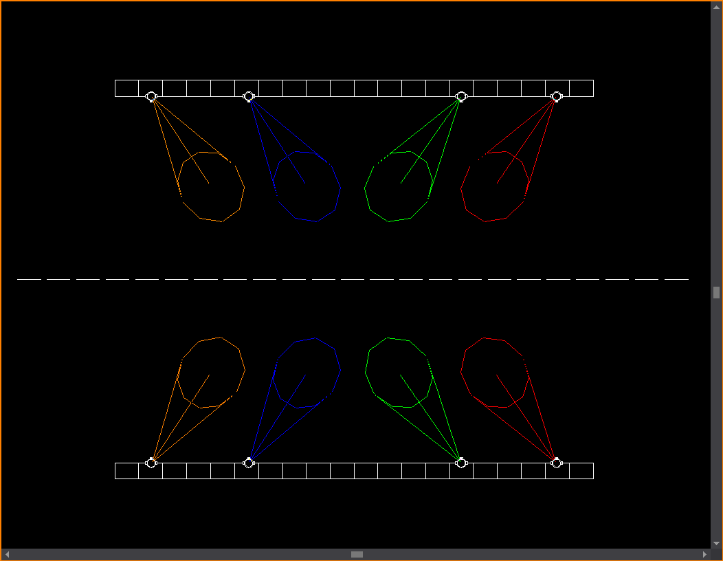
Drawing shapes
Shapes are regular shaped objects comprising
multiple vertices. You can draw Shapes as 2D objects or specify a height
to create 3D objects. You can use shapes to create either wireframe or
solid objects.
Unlike the Surface tool, the Shape tool
gives you the ability to quickly and easily create symmetrical shapes
like squares, pentagons, hexagons, hectagons, and so on. The maximum number
of edges that a shape can have is 40.
Note: Unlike most other tools, the Shape tool does
not have an interactive mode.
To draw a shape
- From
the menu, choose .
 The Shape button.
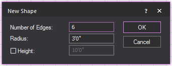
- In the Number of Edges box, type the number of edges or sides of
the shape.
- Specify the Radius (the
distance from the center of the shape to the nearest vertex).
- Select the Height checkbox
if you want to extrude the shape into a 3D object, and then type the
height value in the box provided.
- Click OK to place
the shape in your drawing.
Drawing text labels
Text labels enable you to label different
parts of your drawing for your reference. The labels only appear in wireframe
views and the 3D View.
To change the
Text Label font globally
You can specify the font that you would
like to appear globally in all text labels, both new and existing.
- In any drawing mode, from the .
- Click the Font tab.
- Under Text Labels (Drawing Wireframe), from the
Font drop-down list, select the font
that you want to appear in all new text labels.
- Choose whether you want the letters to appear
bold, underlined, or in italics.
- Click OK.
To draw a text label
- From the menu,
choose .
Tip: You can also use the Text
Label tool on the Draw toolbar.
 The Text
Label button.
The Text
Label button.
Result: The New Text Label
window appears.
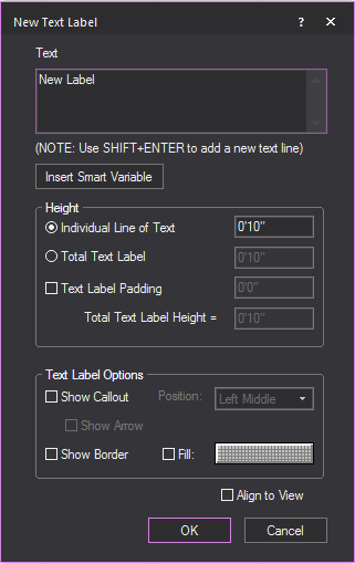
- In the New Text Label window,
in the Text box, type the desired text.
Note: Use SHIFT+ENTER
to add new text lines.
Tip: You can also type text labels with information
listed in the Event Info table using smart variables %Variable
Name% in New Text Label. The information
will be displayed automatically. For example, use %Director% and
the name of the Director stored in the table will appear in the Text Label.
- Click Insert Smart Variable to
open the Smart Variables window where
you can select the smart variable names and values that are listed
in the Event Info tab in Document
Options.
Result: The Smart Variables
window appears.
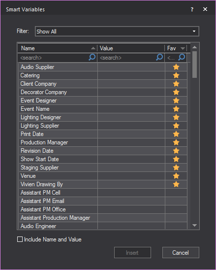
- From the table in the Smart
Variables window, click on the name, translated name,
or value that you want to insert in the text box.
Tip: Click the Filter drop-down
and choose which information to display in the table. See “Event
Info tab”.
- Select the Include Name
and Value checkbox to display both texts under the name
and value columns, or you can leave the checkbox clear to display
only the texts under the value column.
- Click Insert.
Result: The smart variable text appears in the Text box of the New
Text Label window.
- Using the radio buttons, choose how you want to
specify the Height of the Text Label, and enter the value in the corresponding
field.
- Individual Line of Text: Each line of text will be the chosen height.
The text label will change size to accommodate the height.
- Total Text Label: The total text box will be the chosen height.
Text will change size to accommodate the height.
- To add space between the text and the boarder
of the text label, select the checkbox next to Text
Label Padding, and enter the value of the padding in the field.
Note: The Total Text Label
Height field will tell you the exact height of the text label
based on your choices.
- To add a callout to the text label, select the
Show Callout checkbox.
- From the Position drop-down
menu, select where the callout will be located on the text label.
- To have an arrow at the end of the callout, select
the Show Arrow
checkbox.
- To add a border to the text label, select the
Show Border checkbox.
- To fill the text label with color, select the
Fill checkbox.
- Click the Color Selector button to choose the color that will fill
the text label.
- To align the text label to the current view, select
the Align to View checkbox.
- To insert the text label, click OK.
Result: The New Text Label window
closes and you will be in the Wireframe view.
Note: If the Callout checkbox
was selected in the New Text Label window,
the first click in Wireframe view
will be the arrow's position, and the second position will place the text
label.
- Click on the drawing to place the text label.
Result: The text label will be placed.

Notes:
- To change the font of existing text labels in
wireframe modes, see “ To change the font of Text Labels ” below.
- The insertion point for the text label is at
the intersection of the crosshairs.
To change the font of Text
Labels
To change the font of existing labels,
you must do so individually through the label’s Properties window.
- Select the text label whose font you want to change.
- Right-click, and then choose .
- Click the Text Label
tab.
- Under Font, clear
the Use Document Defaults checkbox.
- From the Font drop-down
list, select the new font.
- Choose whether you want the letters to appear
bold, underlined, or in italics.
- Click OK.
To set alignment for a text label
- Select the text label for which you want to change
the alignment.
- Right-click and choose .
- Click the Text Label
tab.
- Set the horizontal and vertical justification
as desired.
- Select the Align to View checkbox
to ensure the text label is legible in all view types (plan, left,
right, front, back, and 3D).
- Click OK.
Result: The text label relocates around the insertion
point based on the options selected.
Drawing
dimensions
Dimensions are 2D objects that help you
measure different aspects of your drawing. There are several types of
dimensions that you can draw in Vivien:
 Linear dimension
lines.
Linear dimension
lines.
 Continue
dimension lines.
Continue
dimension lines.
 Baseline
dimension lines.
Baseline
dimension lines.
 Arc length
dimensions.
Arc length
dimensions.
 Radial dimensions.
 Angle dimensions.
 Linear scale.
You can also use the angle dimension tool
to define precise angles in your drawing, which helps when verifying angular
measurements, and can act as a guide for the drawing process.
Drawing
linear dimension lines
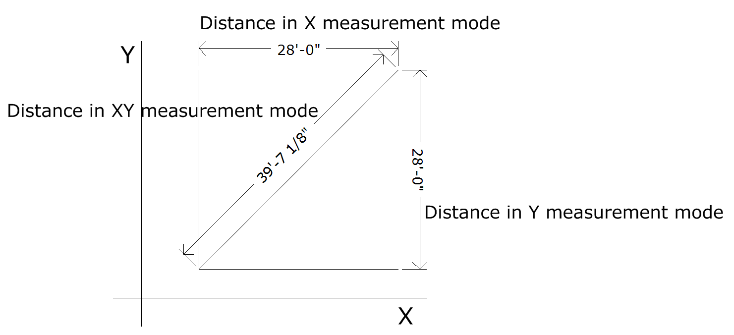
Dimension lines are 2D objects that measure
and display the distance between two points based on the selected measurement
mode. The measurement mode describes which axis the distance is measured
along.
In Vivien Virtual Event Designer,
the measurement modes available are: X, Y, XY, XZ, YZ and XYZ.
For example, in an XY plane, the X measurement
between two points is the distance along the X axis between the two points,
as shown in the following picture.
The dimension is visible only in one view
type. The view type is set when the dimension is drawn and is dependent
on the view type and workplane in which the dimension is drawn.
To draw a linear dimension
- From the menu,
choose > .
Tip: You can also click the Linear
Dimension tool on the Draw toolbar.
 The Linear Dimension button.
- Click on the drawing to set the dimension start
point.
- Right-click to set the measurement mode.
Tip: In measurement mode, you can choose Multiple, which enables you to draw multiple
Linear Dimensions, using the last point of the previous measurements as
the initial point for the next measurement.
- Click on the drawing to set the dimension end
point.
- Click and drag the grab point in the center of
the dimension text to drag the text to the correct side of the object,
if required.
- Click to set the dimension line.
Tips:
- Use snaps to connect dimensions directly to other
objects.
- You can set the rotation angle of the Linear
Dimension to rotate the extension lines around the dimension end points.
The rotated Linear dimension will then display the distance between
the two points at the angle specified. Right-click on the Linear Dimension
and select .
- You can change the Fill color behind the dimension
text of the Linear Dimension. Right-click on the Linear Dimension
and select .
- You can select Display Dash in the Dimensions
tab of Document Options to display
the linear dimensions with a dash between foot and inches in imperial
measurements (e.g. 19’-3 11/16”).
- To change the font used in all dimensions, click
the FontsDocument Options. In the Dimensions (Drawing Wireframe) section, select
the font options to be used in all dimensions.
Drawing
continue dimensions
Continue dimensions display sequential
chains of linear measurements that are aligned to the start (base) measurement
of the Continue Dimension, always using the last point of the previous
measurement as the initial point of the next measurement.
To draw a continue dimension
- From the menu,
choose .
Tip: You can also click the Continue
Dimension tool on the Draw toolbar.
 The Continue Dimension button.
Note: You can also start the Continue Dimension
on an existing Linear Dimension.
- Click on the drawing to set the dimension start
point.
- Click on the drawing to set the next point and
direction of the subsequent measurements in the Continue Dimension.
- Repeat setting the next point and direction to
continue on the subsequent dimensions.
- Right-click on the drawing to set the dimension
end point.
Note: After completing a Continue Dimension, the
measurements created are individual Linear Dimensions.
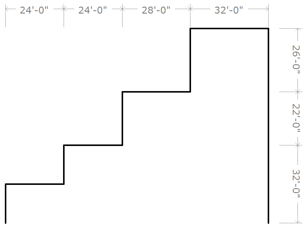
Example: Continue Dimension
Drawing
baseline dimensions
Baseline dimensions display linear measurements
stacked above or below the Base Dimension while maintaining uniform spacing
between, always using the first click as the initial coordinate for all
subsequent measurements.
To draw a baseline dimension
- From the menu,
choose .
Tip: You can also click the Baseline
Dimension tool on the Draw toolbar.
 The Baseline Dimension button.
- Click on the drawing to set the dimension start
point.
- Click on the drawing to set the end point of the
first Baseline Dimension.
- Click on the drawing to set the position (above
or below) for the next/subsequent Baseline Dimension.
- Click on the next point to complete the next Baseline
Dimension measurement, and set the direction of the subsequent measurement.
- Repeat setting the next point to create the subsequent
Baseline Dimensions.
- Right-click on the drawing to set the dimension
end point.
Note: After completing a Baseline Dimension, the
measurements created are individual Linear Dimensions.
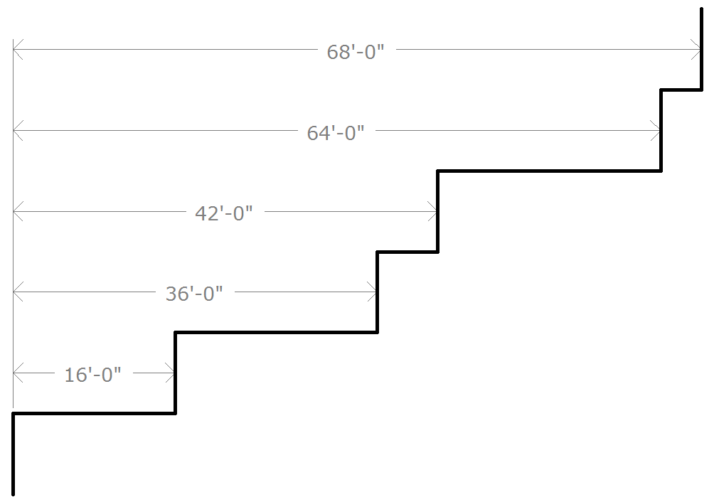
Example: Baseline Dimension
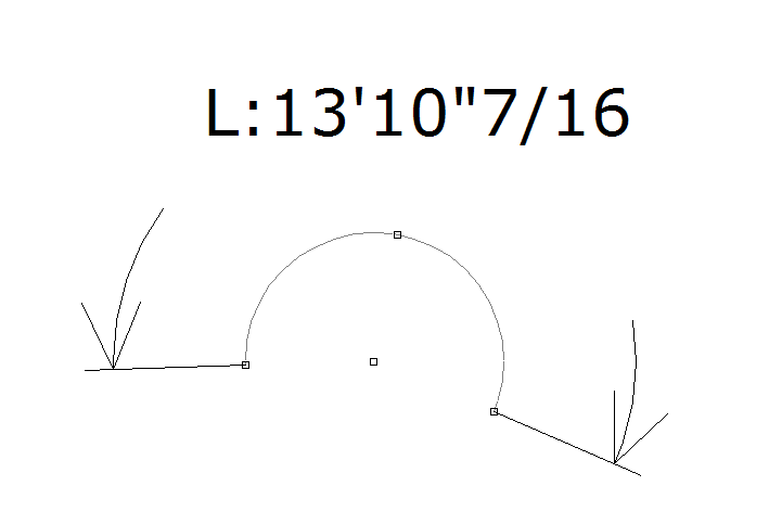
Drawing arc length dimensions
The arc length can be displayed for any
arc drawn in the Drawing Wireframe/Quad. Once enabled, the arc length
dimension is attached to the arc and automatically updates itself whenever
the arc is changed. The dimension is only visible in the view type in
which it was drawn. Although the arc length dimension is attached to the
arc, it is a separate entity. Each arc length is individually selectable
and has its own properties. Arc length dimensions can be separated onto
their own layers, and given their own colors and line weights.
To draw an arc length dimension
- In a Drawing Wireframe, select the arc for which
you want to display an arc length dimension.
- From the menu,
choose .
Tip: To adjust the font used in all dimensions
and with the Angle Dimension tool, click the
FontsDocument Options. In the Dimensions
(Drawing Wireframe) section, select the font options to be used
in all dimensions and with the Angle Dimension
tool.
Drawing radial
dimensions
The radius of a circle/arc is defined as
the distance from the center of a circle/arc to its perimeter. The radius
can be displayed for any circle or arc drawn in the Drawing Wireframe/Quad
tabs. Once enabled, the radial dimension attaches to the circle/arc and
automatically updates itself whenever the circle/arc is changed. Note
that the dimension is only visible in the view type in which it was drawn.
Although the radial dimension is attached to the arc, it is a separate
entity with its own properties and can be individually selected. Radial
dimensions can be separated onto their own layers, and given their own
colors and line weights.
To draw a radial dimension
- In Drawing Wireframe, select the circle/arc for
which you want to display a radial dimension.
- From the menu,
choose .
 The Radial Dimension button.
Tip: To adjust the font used in all dimensions,
click the FontsDocument Options. In the Dimensions
(Drawing Wireframe) section, select the font options to be used
in all dimensions.
Drawing
angle dimensions
The Angle Dimension object measures and
displays an angle, either in Line Select, between two intersecting lines
and objects, or as drawn in Freehand mode.
To draw an angle dimension in Line Select
- From the menu,
choose .
 The Angle Dimension button.
- Choose Line Select from
the Dimension Draw Options dialog box.
- Click on the first line segment in the drawing.
- Click on the second line segment in the drawing.
Result: The
angle between the two selected lines is displayed.
To draw an angle dimension in Freehand
- From the menu,
choose .
 The
Angle Dimension button.
The
Angle Dimension button.
- Choose Freehand in
the Dimension Draw Options dialog box.
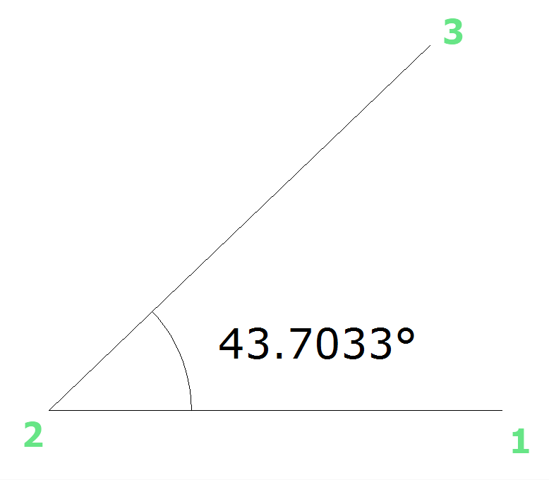
- Click once to define the vertex of the angle (this
is the point at which the two lines of your angle meet, shown as point
number 2 in the diagram above).
- Click a second time to define the first end point
(point number 1 in the diagram above).
- Click a third time to define the second end point
(point number 3 in the diagram above).
Result: The new object displays the interior (or exterior)
angle defined by the two lines.
Tips:
- You can change the Angle Dimension option of
measuring the exterior or interior angle by toggling the Flip
Angle checkbox in the Angle Dimension Properties window.
Simply select the protractor, right-click and choose > Angle Dimension
tab.
- To adjust the font used in all dimensions and
with the Angle Dimension tool, click the FontsDocument Options.
In the Dimensions (Drawing Wireframe)
section, select the font options to be used in all dimensions and
with the Angle Dimension tool.
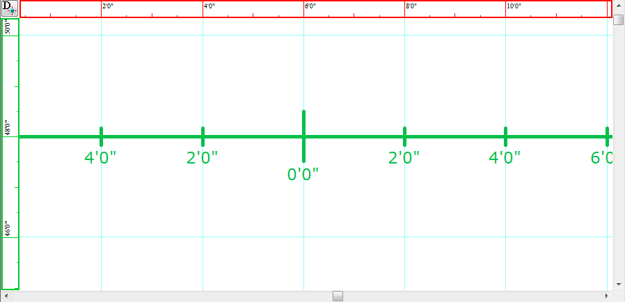
Drawing
linear scales
A linear scale is a visible line divided
into equal proportions used to compare distances in a Vivien drawing to
actual distances.
There are two ways in which you can draw
linear scales:
- Non-freehand mode in which you type the exact
information of the linear scale.
- Freehand mode in which you click and drag to set
the dimensions of the linear scale.
To draw a linear scale
- From the menu,
choose .
 The Linear Scale button.
Result: The
New Linear Scale window appears.
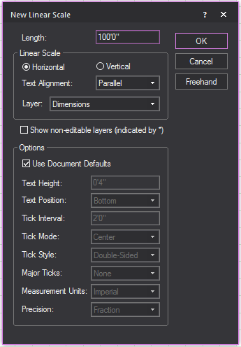
- In the Length field,
enter in the desired length of the linear scale.
- Select either Horizontal or
Vertical to determine how the line
scale is positioned.
- From the Text Alignment drop-down list, choose how the linear scale
text will be presented.
- From the Layer drop-down
list, choose in which layer the linear scale will be visible.
- To change the default document settings of the
linear scale, clear the Use Document Defaults
checkbox.
- Click OK.
Result: The linear scale is attached to the cursor.
- Click to place the linear scale in the drawing.
Drawing walls
Walls are 2D objects that describe flat
rectangular planes representing walls in your drawing. Walls can have
different hatching styles for easy identification in the plot.
There are two ways to draw a wall:
- Specify the width and height and place the wall
in the drawing.
- Draw the wall freehand.
To draw a wall
- From the menu,
choose .
or
Click the Wall tool
on the Draw toolbar.
 The Wall button.
- In the Width box,
enter the width for the wall. The default value is 12’0”.
- In the Height box,
enter the height of the wall. The default value is 8’0”.
- Click OK.
Result: The wall attaches to the cursor.
- Move the cursor to the desired position for the
wall, and then click to place it in the drawing.
To draw a wall in Freehand mode
- Switch to Freehand mode, if you are not already
in it, by clicking the Freehand Mode tool
on the Tools toolbar.
 The Freehand Mode button.
- From the menu,
choose .
- Click to place the start point of the wall.
- Click to place the end point of the wall.
- In the dialog box that opens, enter the missing
dimension of the wall.
- Click OK.
To define the transparency of a wall
- Right-click a wall, and select .
Result: The Propertieswindow appears.
- In the Properties window,
click the Wall tab.

Note: 0% = Opaque, 100% = Transparent.
- To change how the back of the wall will look,
set the Back Transparency field to
the desired transparency percentage.
- To change how the front of the wall will look,
set the Front Transparency field
to the desired transparency percentage.
- Click Apply to enable
the new wall transparency settings.
- Click OK.
Hatching
To
add hatching to an object
Note: Not all objects support hatching. If hatching
is not supported, the checkbox to enable hatching is disabled.
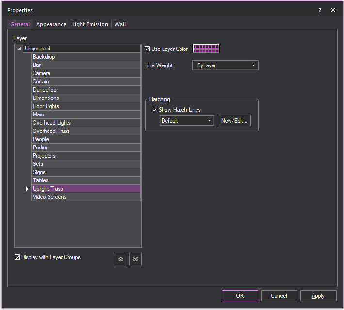
- Right-click the object, and select .
Result: The Propertieswindow appears.

- In the Properties window,
click the General
tab.
- To enable hatching for the object, select the
Show Hatch Lines checkbox.
- Select the desired hatching style for the object
from the Available hatching styles drop-down
menu.
- Click Apply to enable
the hatching style for the object.

Tip: You can also click the menu
and choose to open the Hatch Style Manager window.
To edit or create a hatching style
- Right-click an object that supports hatching,
and select .
Result: The Propertieswindow appears.

- In the Properties window,
click the General
tab.
- To enable hatching for the object, select the
Show Hatch Lines checkbox.
- To make a new hatch style or edit an existing
style, click New/Edit....
Result: The Hatch Style Manager window appears. All existing hatch styles
are displayed and can be edited here.
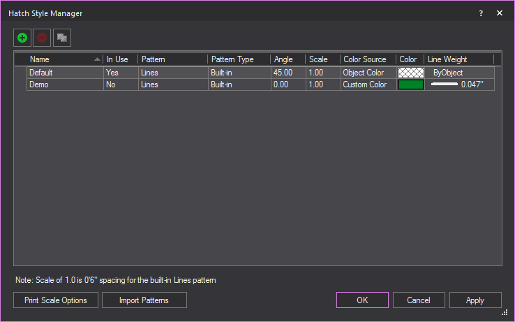
- To create a new hatch style, click the New
Hatch Style button.
 The New Hatch Style button.
Result: The New
Hatch Style window appears.

- In the New Hatch Style window,
enter the details of the new hatch style.
- Click OK.
- Click Apply to enable
the new styles.
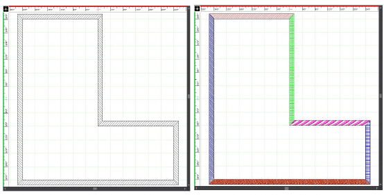
Walls with the default hatching styles
applied (left) and the same walls with custom hatching styles (right).
To clone a hatching style
- Right-click an object that supports hatching,
and select .
Result: The Propertieswindow appears.

- In the Properties window,
click the General
tab.
- Select the Show Hatch Lines
checkbox.
- Click New/Edit....
Result: The Hatch Style Manager window appears. All existing hatch styles
are displayed and can be edited here.

- To clone an existing hatching style, select the
style you want to copy and click the Clone Hatch
Style button.
 The
Clone Hatch Style button.
The
Clone Hatch Style button.
Result: The Clone
Hatch Style window appears. All the settings of the selected
hatch style will be copied into the window.
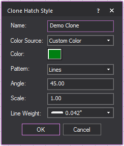
- In the Clone
Hatch Style window, edit any hatching setting that you
want to be different from the original hatching style.
- Click OK.
Result: The cloned hatching style appears in the Hatch Style Manager window and available for
use.
To delete a hatching style
- Right-click an object that supports hatching,
and select .
Result: The Propertieswindow appears.

- In the Properties window,
click the General
tab.
- Select the Show Hatch Lines
checkbox.
- Click New/Edit....
Result: The Hatch Style Manager window appears. All existing hatch styles
are displayed.

- To delete an existing hatching style, select the
style you want to remove and click the Delete
Hatch Style button.
 The Delete Hatch Style button.
Result: The Delete
Hatch Style window appears.
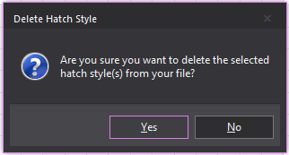
- In the Delete
Hatch Style window, to delete the hatch style click Yes.
Result: The selected hatching style is removed from
Vivien.
To change the print scale of hatching styles
Spacing for built-in line patterns found
in hatching use a default scale of 1.0 equal to 0’6” (2.54 cm). Print Scale Options can be used to create
a different scale when printing in Presentation mode.
- Right-click an object that supports hatching,
and select .
Result: The Propertieswindow appears.

- In the Properties window,
click the General
tab.
- Select the Show Hatch Lines
checkbox.
- Click New/Edit....
Result: The Hatch Style Manager window appears. All existing hatch styles
are displayed.

- Click Print Scale Options.
- The Print Scale Options
window appears.
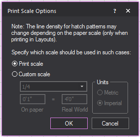
- In the Print Scale Options window,
to create a custom print scale, select the Custom
scale radio button.
Note: To revert the print scale to its default settings,
select the Print scale
radio button.
- Edit the print scale settings as desired.
- Click OK.
- Click Apply.
Result: The print scale options change.
To import hatching patterns
To import Hatch Pattern files (.pat files),
save these files in the folder location that was entered as the Hatch Pattern Files location in the File Locations tab in the Application
Options window. When you restart Vivien, these patterns will
be listed in the Hatch Style Manager.
- Right-click an object that supports hatching,
and select .
Result: The Propertieswindow appears.
- In the Properties window,
click the General
tab.
- Select the Show Hatch Lines
checkbox.
- Click New/Edit....
Result: The Hatch Style Manager window appears. All existing hatch styles
are displayed.

- Click Import Patterns.
Result: The Application Options
window appears.
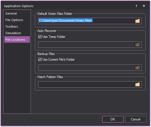
- In the Application Options window, enter the location of the hatch
pattern files (.pat files) in the Hatch Pattern
Files field.
- Click OK.
Result: A dialog box appears warning that Vivien needs
to restart to display the imported hatching patterns in the Hatch
Style Manager.
Drawing
risers
Risers are solid 3D rectangular objects.
Risers can be used for creating platforms, square columns, or any other
box-shaped objects.
There are two ways to draw a riser:
- Specify the width, depth, and height, and then
place the riser on the drawing.
- Draw the riser freehand.
Note: Risers appear two-dimensional when you are
in Plan, Left, Right, Front, and Back views. To see risers in three dimensions,
switch to 3D view in Vivien Virtual Event Designer.
To draw a riser
- From the menu,
choose .
or
Click the Riser tool on the
Draw toolbar.
 The Riser button.
Result: The New riser
dialog box opens.
- In the Width box,
enter the width for the riser. The default value is 8’0”.
- In the Depth box, enter the depth for the riser. The
default value is 4’0”.
- In the Height box,
enter the height for the riser. The default value is 2’0”.
- Click OK.
Result: The riser attaches to the cursor.
- Move the cursor to the desired position for the
riser, and then click to place it in the drawing.
To draw a riser in Freehand mode
- Switch to Freehand mode, if you are not already
in it, by clicking the Freehand Mode tool
on the Tools toolbar.
 The Freehand Mode button.
- From the menu,
choose .
 The Riser button.
- Click the starting point of the riser on the drawing.
The insertion point is the lower left corner of the riser.
- Drag in any direction to stretch out the riser’s
shape. Click to place the upper right corner of the riser.
- In the dialog box that opens, type the missing
dimension of the riser.
- Click OK.
Drawing
cylinders
Cylinders are solid 3D cylindrical objects.
You can use cylinders to create platforms, columns, or any other cylinder-shaped
objects.
There are two ways to draw a cylinder:
- Specify the height and radius and place the cylinder
on the drawing.
- Draw the cylinder freehand.
Note: Cylinders appear two-dimensional when you
are in Plan, Left, Right, Front, and Back views. To see cylinders in three
dimensions, switch to 3D view.
To draw a cylinder
- From the menu,
choose .
or
Click the Cylinder tool on
the Draw toolbar.
 The Cylinder button.
Result: The New Cylinder
dialog box opens.
- In the Height box,
enter the height for the cylinder. The default value is 8’0”.
- In the Horizontal Radius box,
type the horizontal radius for the cylinder. The default value is
4’0”.
- In the Vertical Radius box,
type the vertical radius for the cylinder. The default value is 4’0”.
Note: When the Horizontal and Vertical radii are
the same, a circular object is created; when they are different, the object
is oval-shaped.
- To ensure that the cylinder remains proportionately
the same when resized, leave the Lock Ratio checkbox
checked. If you clear this checkbox, then you can manually resize
the cylinder in any direction, regardless of its original measurements.
- To have the cylinder appear smooth in the Virtual
View, leave the Smooth Shading option
enabled; to see a faceted cylinder in the Virtual View, disable this
option. The default for this option is ON.
- To change the default number of cylinder segments,
clear the Use Document Defaults checkbox
and type the new number of segments. Note that the higher the number
of segments, the better the cylinder will appear in Virtual View,
but the more performance will degrade.
- Click OK.
Result: The cylinder attaches to the cursor.
- Move the cursor to the desired position for the
cylinder, and then click to place it in the drawing.
To draw a cylinder in Freehand mode
- Switch to Freehand mode, if you are not already
in it, by clicking the Freehand Mode tool
on the Tools toolbar.
 The
Freehand Mode button.
The
Freehand Mode button.
- From the menu,
choose .
 The Cylinder button.
- Click to place the center of the bottom surface
of the cylinder.
- Click to set the radius for the cylinder.
- In the dialog box that opens, type the desired
height, horizontal radius, and vertical radius for the cylinder.
- To ensure that the cylinder remains proportionately
the same when resized, leave the Lock Ratio checkbox
checked. If you clear this checkbox, then you can manually resize
the cylinder in any direction, regardless of its original measurements.
- To have the cylinder appear smooth in the Virtual
View, leave the Smooth Shading option
enabled; to see a faceted cylinder in the Virtual View, disable this
option. The default for this option is ON.
- To change the default number of cylinder segments,
clear the Use Document Defaults checkbox
and type the new number of segments. Note that the higher the number
of segments, the better the cylinder will appear in Virtual View,
but the more performance will degrade.
- Click OK.
Drawing
spheres
Spheres are solid 3D circular or oval objects.
There are two ways to draw a sphere:
- Specify the horizontal and vertical radius and
place the sphere on the drawing.
- Draw the sphere freehand.
Note: Spheres appear two-dimensional when you are
in Plan, Left, Right, Front and Back views. To see spheres in three dimensions,
switch to 3D view.
To draw a sphere
- From the menu,
choose .
or
Click the Sphere tool on the
Draw toolbar.
 The Sphere button.
Result: The New Sphere
dialog box opens.
- In the Horizontal Radius box,
type the horizontal radius of the middle diameter of the sphere. The
default value is 4’0”.
- In the Depth
Radius box, type the depth radius of the middle
diameter of the sphere. The default value is 4’0”.
- In the Vertical Radius box,
type the vertical radius of the middle diameter sphere. The default
value is 4’0”.
Note: When the Horizontal, Depth and Vertical radii
are the same, a circular 3D object is created; when they are different,
the 3D object is oval-shaped.
- To ensure that the sphere remains proportionately
the same when resized, leave the Lock Ratio checkbox
checked. If you clear this checkbox, then you can manually resize
the sphere in any direction, regardless of its original measurements.
- To change the default number of sphere segments
and stacks, clear the Use Defaults checkbox
and type the new values for Number of Segments and
Number of Stacks. Note that the higher
the number of segments or stacks, the better the sphere will appear
in Virtual View, but the more performance will degrade.
- To have the sphere appear smooth in the Virtual
View, leave the Smooth Shading option
enabled; to see a faceted sphere in the Virtual View, disable this
option. The default for this option is ON.
- Click OK.
Result: The sphere attaches to the cursor.
- Move the cursor to the desired position for the
sphere, and then click to place the object in the drawing.
To draw a sphere in Freehand mode
- Switch to Freehand mode, if you are not already
in it, by clicking the Freehand Mode tool
on the Tools toolbar.
 The Freehand Mode button.
- From the menu,
choose .
 The Sphere button.
- Click to place the center of the sphere.
- Click to set the radius for the sphere.
- In the dialog box that opens, enter the desired
horizontal and vertical radius for the sphere.
- To ensure that the sphere remains proportionately
the same when resized, leave the Lock Ratio checkbox
checked. If you clear this checkbox, then you can manually resize
the sphere in any direction, regardless of its original measurements.
- To change the default number of sphere segments
and stacks, clear the Use Defaults checkbox
and type the new values for Number of Segments and
Number of Stacks. Note that the higher
the number of segments or stacks, the better the sphere will appear
in Virtual View, but the more performance will degrade.
- To have the sphere appear smooth in the Virtual
View, leave the Smooth Shading option
enabled; to see a faceted sphere in the Virtual View, disable this
option. The default for this option is ON.
- Click OK.
Drawing
cones
Cones are solid 3D objects.
There are two ways in which you can draw
cones:
- Non-freehand mode in which you type the exact
horizontal and vertical radius of the cone.
- Freehand mode in which you click and drag to set
the dimensions of the cone
To draw a cone
- From the menu,
choose .
Note: You can also click the Cone tool
on the Draw toolbar.
 The Cone button.
- In the Height box,
type the height of the cone.
- In the Horizontal Radius box, type the horizontal radius for the
cone.
- In the Vertical Radius
box, type the vertical radius for the cone.
Note: When the Horizontal and Vertical radii are
the same, a circular object is created; when they are different, the object
is oval-shaped.
- To ensure that the cone remains proportionately
the same when resized, leave the Lock Ratio checkbox
checked. If you clear this checkbox, then you can manually resize
the cone in any direction, regardless of its original measurements.
- To change the default number of cone segments
and stacks, clear the Use Defaults checkbox
and type the new values for Number of Segments and
Number of Stacks. Note that the higher
the number of segments or stacks, the better the cone will appear
in Virtual View, but the more performance will degrade.
- To have the cone appear smooth in the Virtual
View, leave the Smooth Shading option
enabled; to see a faceted cone in the Virtual View, disable this option.
The default for this option is ON.
- To enable hatching for the object, select the
Show Hatch Lines checkbox.
- Select the desired hatching style for the object
from the Hatch Style drop-down menu.
- Click OK.
Result: The cone is attached to the cursor.
- Click to place the cone in the drawing.
To draw a cone in Freehand mode
- From the menu,
choose .
Note: You can also click the Cone tool
on the Draw toolbar.
 The Cone button.
- In the New Cone window,
click Freehand.
- Accept the default values, and then click and
drag out the shape of the cone in your drawing. When you have the
desired size, click again.
Result: The New Cone window
appears again.
- In the dialog box that opens, type the height
and the horizontal and vertical radius of the new cone.
- To ensure that the cone remains proportionately
the same when resized, leave the Lock Ratio checkbox
checked. If you clear this checkbox, then you can manually resize
the cone in any direction, regardless of its original measurements.
- To change the default number of cone segments
and stacks, clear the Use Defaults checkbox
and type the new values for Number of Segments and
Number of Stacks. Note that the higher
the number of segments or stacks, the better the cone will appear
in Virtual View, but the more performance will degrade.
- To have the cone appear smooth in the Virtual
View, leave the Smooth Shading option
enabled; to see a faceted cone in the Virtual View, disable this option.
The default for this option is ON.
- To enable hatching for the object, select the
Show Hatch Lines checkbox.
- Select the desired hatching style for the object
from the Hatch Style drop-down menu.
- Click OK.
- Click in the drawing to finish placing the new
cone.
Drawing
surfaces
Surfaces are 2D objects that describe flat
planes. You can use surfaces to create backdrops or other flat objects.
Surfaces can be 3D Transformed to create odd shaped risers, or other custom
shaped 3D objects. For more information on 3D transforming, “Transforming
objects into surfaces or 3D surfaces”.
When you draw multi-segmented lines or
surfaces, the new line or surface snaps automatically to the previously
drawn line or surface’s endpoint, midpoint or intersection when the Endpoint Snap, Midpoint
Snap, or Intersection
Snap are enabled.
Note: The beam will pass through a surface with
the Transparency value set to 80% or greater. The beam will not pass through
the surface when the value is lower than 80%. Transparency value is set
in the Material Properties section in
the Appearance tab of the Properties window.
See “Appearance
tab”.
To draw a surface
- From the menu,
choose .
or
Click the Surface tool
on the Draw toolbar.
 The
Surface button.
The
Surface button.
- Click on the drawing at the starting point of
the surface.
- Move the pointer to the next point of the surface
and click.
- Continue to place points for the surface as needed.
- To finish and close the surface, right-click and
choose .
To cancel the drawing of the surface, right-click
and choose . This erases the whole
surface from the drawing.
Surfaces
as Curtains
Vertical surfaces can have their appearance
changed to mimic the look of curtains in Plan View. The curtain will appear
as a wave or semicircles pattern, instead of the usual straight line of
a surface. The depth, width and number of segments in the curtain pattern
can be customized.
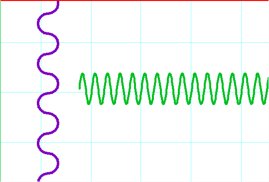
A Plan view of example surfaces. A surface
with semicircle curtain enabled in purple and a surface with wave curtain
enabled in green.
Note: Curtains are limited to being visible only
in Plan view, with a surface that is vertical and rectangular in shape,
with no surface area visible in Plan View.
To display a surface as a curtain.
- Right-click an eligible surface and select .
- In the Properties window,
click the Surface tab.

- To enable the curtain feature for the surface,
select the Enable checkbox.
Note: If the surface is ineligible to be a curtain,
this option will be grayed out.
- Select from the Style drop-down
menu which pattern of curtain should be displayed.
- Enter the desired depth of the curtain pattern
in the Depth field.
- Enter the desired width of the curtain pattern
in the Width field.
- Enter the desired number of segments in the curtain
pattern in the Number of Segments field.
- Click Apply.
Drawing
hang structures
Some light fixtures need to be suspended,
or hung. The structures they are hung on are called “hang structures”
(also known as truss). You can draw many different types of truss, including
pipes, ladders, boxes, and triangles, with the Truss
Wizard. You can even specify whether the truss points in an upward
or downward direction, which makes it easy to create uplighting effects.
Tip:
If you want to build more complex and realistic truss structures, you
can use the Truss pieces in the AV category
of Library Browser. Truss pieces from the
Library Browser represent real-life truss
structures used for actual events and shows. For information on how to
use Truss from the Library Browser, see Using truss from Library.
To hang truss using
Truss Wizard
- From the menu,
choose .
or
Click the Truss Wizard tool on the Draw toolbar
to place truss.
 The
Truss Wizard button.
The
Truss Wizard button.
Result: The Truss Wizard
dialog box opens.
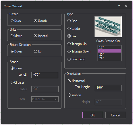
- Select whether you want to Draw the
truss or Specify the dimensions and
place it automatically.
- Select whether you want the truss measurements
to be specified in metric or imperial units.
- Select the direction in which the fixtures will
face when hung from the truss. Note that this does not apply to the
Floor Base type of truss since all fixtures hung from this truss type
always point upwards.
- Down: Select this
option to have all fixtures hung from this piece of truss shine downward.
This is the default value.
- Up: Select this option
to have all fixtures hung from this piece of truss shine upward.
- Select the type of truss you are adding: Pipe, Ladder, Box, Triangle Up or
Triangle Down,
or Floor Base. A preview image
of the selected truss displays beside the selection.
Note: When you select the Floor
Base truss, any fixtures attached to it always point upwards.
- For all types other than Pipe and Floor Base, select a Cross
Section measurement.
- For all types other than Floor
Base, select the shape of the truss: Linear or
Circular.
- If you selected to specify the truss, rather than
draw it in step 2:
- To draw a linear truss, in the Length box,
enter the length of the truss.
Note: The
minimum length of a linear pipe is 6”; the minimum length of a piece of
linear truss is 2’.
- To draw a circular truss, in the Radius box,
enter the radius of the truss and select the form of the circle.
Notes:
- Use the Form drop-down
menu to create a Half-Circle or Quarter Circle truss object.
- The minimum length of a circular truss is 4’.
- Select to have the truss inserted horizontally
or vertically. In the Height box,
enter the trim height for the piece of truss. The trim height represents
the height at which the truss is inserted in the file. For truss inserted
with a Down Fixture Direction, the trim height is measured from the
bottom pipe of the truss; for truss inserted with the Up Fixture Direction,
the trim height is measured from the top pipe of the truss.
- Select whether the orientation of the truss should
be Horizontal or Vertical.
Specify the Trim Height/Height
in the field.
- Click OK.
- If you selected Draw,
click on the drawing where you want the truss to start and then click
to place the endpoint of the truss
Result: The truss is placed according to your settings.
Drawing
projectors and screens
You can use the Projection
Wizard to draw your choice of a number of different types
of screens and projectors. If desired, you can then navigate to an image
stored in bitmap (.bmp) or jpeg (.jpg) format and place it on the screen.
The Projection Wizard is especially useful
to give you an idea of the spacing you will need to arrange in your venue
to set up the projector and screen for optimum viewing.
Note: While the Projection
Wizard provides a realistic depiction of the spacing required,
and the look of the projector and screen, it does not enable you to specify
the method for hanging or mounting the projector. Instead, use your Vivien
drawing as a guide to hang or mount the projector at the precise location
indicated.
You can use the Projection
Wizard to draw both a
projector and screen, in which case the two are treated as a grouped object,
or you can choose to create only a
projector or a screen. In this latter case, you can return to the wizard
later to add either the projector or screen, working your way through
the Projection Wizard again. The Projection
Wizard saves the settings that you originally chose for the projector
or screen, and enables you to add the other object as a grouped item.
Projector and screen types
The Projection
Wizard enables you to choose from three main screen types,
and then customize the screen to suit your needs. When drawing projectors,
you can choose between generic small, medium, and large models; you cannot
choose brand name models.
To properly calculate the distance from
the projector to the screen, you must know the size of the screen, as
well as the projector’s aspect ratio and the lens throw ratio (refer to
the projector specifications for these values). After you input these
values, Vivien will calculate the appropriate throw distance for you (the
distance from the projector to the screen), as well as the projected image
width.
To draw a projector and
screen
This procedure shows you how to draw a
projector and screen together. You can choose from three different types
of screens and three different sizes of projector. When you create a projector
and screen in this manner, they are treated as a single, grouped object,
enabling you to change their properties simultaneously, if necessary.
- From the menu,
choose .
 The Projection
Wizard button.
The Projection
Wizard button.
Result: The Projection Wizard
window appears.
- Click Create Both,
and then click Next.
- Select the type of screen that you want to create,
and then click Next. You can choose from
the following screen types:
- Tripod Screen: This
type of screen sits on a tripod and is typically used in smaller venues
because the screen size is usually limited to no larger than 10’ X
10’. When drawing this type of screen, you can specify the screen
size, the distance from the screen to the ground, and the diameter
of the circle formed by the legs of the tripod.
- Folding Screen: This
type of screen consists of up to 6 main components: the frame, legs,
surface, valance, drape legs, and skirt. When drawing this screen,
you can choose from a list of industry-standard screen sizes, or specify
the screen size of your choice. You can also choose whether the screen
is surrounded by a drape and, if so, you can choose the dimensions
of the drape panels.
- Custom Surface: Unlike
the other two screen types available, custom screens do not have a
frame around them. When you choose this type of screen, you can specify
the size of the screen, or choose from a predefined list of standard
screen sizes.
Result: The window that appears varies according to
the type of screen that you chose.
- Type the properties of your screen in the appropriate
fields below:
- Predefined Size:
From the drop-down list, select the standard size of screen that you
want to create. If you want to specify a non-standard size, choose
Custom.
- Width: Indicates
the width of the standard sized screen. If you chose to create a custom-sized
screen, type the custom width.
- Height: Indicates
the height of the standard sized screen. If you chose to create a
custom-sized screen, type the custom height.
- Elevation Above Floor:
(only applicable for Folding and Tripod screens) Type the height of
the tripod or support frame.
- Tripod Diameter:
(only applicable for Tripod screens) Type the diameter of the circle
created by the tripod legs.
- Length of Support Feet:
(only applicable for Folding screens) Type the length of each of the
supporting “feet” for the frame of the screen.
- Include Drape Kit:
(only applicable for Folding screens) Select this checkbox if you
want to hide the frame of the screen with drapery panels. If you do
not check this box, the frame around the screen is visible.
- Click Next.
Result: Only if you are creating a Folding screen
and if you chose to include
the drape kit, the Define Drape Kit Dimensions window
appears.
Note: If you are creating any other type of screen
or if you have decided to hide the drape kit, then
the Content Selection window appears.
Proceed directly to step 8.
- Type the dimensions of the drape kit around the
Folding screen. If you do not want to see part of the drape kit, clear
the checkbox beside the appropriate heading (for example, if you do
not want to see the skirt, clear this checkbox).
- Click Next.
Result: The Content Selection
window appears.
- Choose whether you want to draw a blank screen,
show an image, or play a video on it.
- To show an image, click Image
Source, and select the desired image previously imported by
the Image Manager. Or, click New to
open the Image Manager and create
a new image for use. “To
create a new image source in the image manager” for
more information.
- To show an video, click Video
Source, and select the desired video previously imported by
the Video Manager. Or, click New to
open the Video Manager and create
a new video for use. “To
create a new video source in the video manager” for more
information.
Note: Video codecs may be required to play the video
even though it is already an “.avi” or “.mpg” file.
- Click Next.
Result: The Define Projector
Specifications window appears.
- Enter the properties for your projector in the
appropriate boxes:
- Aspect Ratio: This
is the width-to-height ratio of the displayed image. Refer to the
projector specifications for this value. Note that some projectors
can support multiple aspect ratios. The following aspect ratios are
available for you to choose from:
- 1:1: Provides
a perfectly squared screen format for native SVGA/XGA projectors.
- 5:4: For images
with SXGA resolution. Widescreen images will appear cropped at
this ratio.
- 4:3: Standard
aspect ratio for TV, as well as for images with VGA, SVGA, XGA,
or UXGA resolution. Widescreen images will appear cropped at this
ratio.
- 3:2: For classic
35mm film with 24mm x 36mm image size.
- 16:9/16:10: For
wide-screen images, this aspect ratio shows you a picture that
is about one-third wider than standard displays. It is the format
for HDTV video and some SDTV video.
- 1.85:1: For 35mm
widescreen standard theatrical film.
- 1.9:1: Common
aspect ratio supported by social media platforms such as Facebook,
Instagram and Twitter.
- 2.35:1/2.39:1: For anamorphic widescreen cinemascope
format.
- 21:9: For high
end UltraWide monitors.
- 3:1: Standard
aspect ratio for APS-P panorama images.
- Projector Size: Choose
the size of your projector, Small, Medium, or Large. This value is
largely for display purposes in your drawing and does not necessarily
reflect the actual projector.
- Lens
Throw Ratio: Refer to the projector specifications for this
value. It may be lens-specific rather than projector-specific because
some projectors can support multiple lenses. It is equal to the throw
distance divided by the projected image width. For a projector without
a zoom lens, the throw ratio is fixed (the size of the projected image
is completely determined by the throw distance and aspect ratio).
However, for a projector with a zoom lens, you can change the throw
ratio (you can control the image size without having to change the
throw distance).
Note: Once you input the throw ratio and aspect
ratio, Vivien will calculate the projector’s throw distance for you.
- Throw Distance: The
formula for calculating the throw distance is Throw Ratio * Width
of Screen. Some lenses are wider-angle (they cover short throw distances),
while others are more in the tele-range (they cover large throw distances).
Once you input the screen width, and the aspect ratio and throw ratio
for your projector, Vivien will adjust the throw distance accordingly.
- Image Width (read-only):
Vivien automatically calculates this value based on the screen width
and height that you chose, as well as the projector’s aspect ratio
that you just typed. If the Image Width shown in this box is smaller
than the screen width that you entered earlier, it is because the
specified screen height is too small and, as a result, limits the
width of the image to maintain the requested aspect ratio. If you
want the image width to be the same as the screen width, then you
must increase the screen’s height so that its width-to-height ratio
is the same as (or a multiple of) the projector’s aspect ratio. For
example, if the projector’s aspect ratio is 5:4, then you could have
a screen with the dimensions of 10’ wide X 8’ high (for a ratio of
10:8, or 5:4). Click Back twice
to return to the Screen Dimensions window, and then adjust the height
accordingly.
- Front Projection / Rear Projection:
Choose whether you want the projector to throw the image onto the
front or back of the screen. Based on your selection, the projector
will either appear in front of or behind the screen in your drawing.
- Click Finish.
Result: The projector attaches to your cursor.
- Click to place the projector in your drawing.
Drawing screens
In Vivien, you can draw a 2D surface on
which you can place an image to simulate projection onto a screen. To
draw a screen on its own (without a projector), you still use the Projection Wizard, choosing Create
a Screen in the first window.
Note: To add a screen to the drawing after you
have added a projector, select the projector, right-click, and select
Change Projection Settings. When you do so,
the Projection Wizard appears, listing
the existing settings for the projector. As you work your way through
the Wizard to add the screen, you can leave the current projector settings,
or modify them. Based on the settings you choose, Vivien adds the screen
at the appropriate throw distance from the projector. Both objects are
subsequently treated as a single, grouped object.
To draw a screen
- From the menu,
choose .
 The Projection Wizard button.
Result: The Projection Wizard
window appears.
- Click Create a Screen,
and then click Next.
- Select the type of screen that you want to create,
and then click Next. You can choose from
the following screen types:
- Tripod Screen: This
type of screen sits on a tripod and is typically used in smaller venues
because the screen size is usually limited to no larger than 10’ X
10’. When drawing this screen, you can specify the screen size, the
distance from the screen to the ground, and the diameter of the circle
formed by the legs of the tripod.
- Folding Screen: This
type of screen consists of up to 6 main components: the frame, legs,
surface, valance, drape legs, and skirt. When drawing this screen,
you can choose from a list of industry standard screen sizes, or specify
the screen size of your choice. You can also choose whether the screen
is surrounded by a drape and, if so, you can set the dimensions of
the drape panels.
- Custom Surface: Unlike
the other two screen types available, custom screens do not have a
frame around them. When you choose this type of screen, you can specify
the size of the screen, or choose from a predefined list of standard
screen sizes.
Result: The window that appears varies according to
the type of screen that you chose.
- Type the properties of your screen in the appropriate
fields below:
- Predefined Size:
From the drop-down list, select the standard size of screen that you
want to create. If you want to specify a non-standard size, choose
Custom.
- Width: Indicates
the width of the standard sized screen. If you chose to create a custom-sized
screen, type the custom width.
- Height: Indicates
the height of the standard sized screen. If you chose to create a
custom-sized screen, type the custom height.
- Elevation Above Floor:
(only applicable for Folding and Tripod screens) Type the height of
the tripod or support frame.
- Tripod Diameter:
(only applicable for Tripod screens) Type the diameter of the tripod.
- Length of Support Feet:
(only applicable for Folding screens) Type the length of each of the
supporting “feet” for the frame of the screen.
- Include Drape Kit:
(only applicable for Folding screens) Select this checkbox if you
want to hide the frame of the screen with drapery panels. If you do
not check this box, the frame around the screen is visible.
- Click Next.
Result: Only if you are creating a Folding screen
and if you chose to include
the drape kit, the Define Drape Kit Dimensions window
appears.
Note: If you are creating any other type of screen
or if you have decided to hide the drape kit, then
the Content Selection window appears.
Proceed directly to step 8.
- Type the dimensions of the drape kit around the
Folding screen. If you do not want to see part of the drape kit, clear
the checkbox beside the appropriate heading (for example, if you do
not want to see the skirt, clear this checkbox).
- Click Next.
Result: The Content Selection
window appears.
- Choose whether you want to draw a blank screen,
show an image, or play a video on it.
- To show an image, click
Image Source, and select the desired image previously imported
by the Image Manager. Or, click New to open the Image
Manager and create a new image for use. “To
create a new image source in the image manager” for
more information.
- To show a video, click Video
Source, and select the desired video previously imported by
the Video Manager. Or, click New to
open the Video Manager and create
a new video for use. “To
create a new video source in the video manager” for
more information. Video codecs may be required to play the video even
though it is already an .avi or .mpg file.
- Click Finish.
Result: The screen attaches to your cursor.
- In your drawing, move the cursor to the desired
position for the screen, and then click to place it in your drawing.
Note: If you have chosen to place an image on the
screen, it appears only in Virtual View.
Screen
Properties
After a screen has been created, the properties
of a screen can be altered from the properties menu. The following properties
of the screen can be changed:
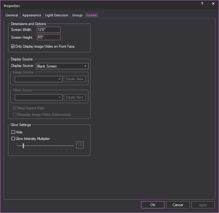
Dimensions and Options
The size of the screen can be changed from
its original dimensions.
- Screen Width: The width of the screen.
- Screen Height: The
height of the screen.
- Only Display Image/Video
on Front Face: Select this checkbox to set the color, Image
Source, or Video Source to appear only on the front side of the screen.
Note: The
front side of a Screen is the one which does not display the “V” symbol
when the Screen appears in Drawing Wireframe set to Plan view.
Tip: The
Only Display Image/Video on Front Face option
will help when using the Global Illumination with
Approximation Method 2 Visual Effect:
when this Visual Effect is enabled, the illumination it produces will
only appear on the front side of the Screen.
Display Source
Options for controlling what will be visible
on the screen.
- Display Source: Drop-down
menu for controlling what will be visible on the screen.
- Image Source: Available
images that can be displayed on the screen.
- Video Source: Available
videos that can be displayed on the screen.
- Keep Aspect Ratio:
Toggle whether to have images/videos displayed on the screen maintain
their aspect ratio or stretch/constrict when the size of the screen
changes.
- Reassign Video/Image Subsource(s):
This checkbox is available when the screen is set with Multi-split
subsources. Select this checkbox to open the Reassign
Video/Image Subsource dialog and reassign the video and
image source types and options for the screen.
Glow Settings
Setting for controlling the glow of the
selected screen, independent of the global settings.
- Hide: Toggle to enable/disable
the screen glow feature.
- Glow Intensity Multiplier:
When enabled can enhance the glow of the screen on a scale of 0 to
10.
Drawing
projectors
You can use the Projection
Wizard to draw a projector on its own (without the screen),
or to add a projector to a drawing in which there is already a screen.
You may want to perform this procedure,
for example, if you are going to project an image onto a wall or other
surface. Even though you are not drawing a screen at the same time, Vivien
will still calculate the throw distance to the projection surface if you
know both its width and the projector’s throw ratio. You can then manually
place the projector in your drawing at this distance from the wall or
screen.
Note: If you want to add a projector to your drawing
after you have drawn a screen
on its own, select the screen, right-click, and choose Change
Projection Settings. When you do so, the Projection
Wizard appears, listing the existing
settings for the screen. As you work your way through the Wizard to add
the projector, you can leave the current screen settings, or modify them.
Based on the settings you choose, Vivien adds the projector at the appropriate
throw distance from the screen. Both objects are subsequently treated
as a single, grouped object.
To draw a projector
This procedure shows you how to draw a
projector on its own, enabling you to choose from three different sizes
of projector. When you create a projector in this manner, it is treated
as a single object (it is not grouped with a screen)
Note: To add a screen to the drawing after you have
added a projector, select the projector, right-click, and select Change Projection Settings. When you do so,
the Projection Wizard
appears, listing the existing settings for the projector. As you
work your way through the Wizard to add the screen, you can leave the
current projector settings, or modify them. Based on the settings you
choose, Vivien adds the screen at the appropriate throw distance from
the projector. Both objects are subsequently treated as a single, grouped
object.
- From the menu,
choose .
 The Projection Wizard button.
Result: The Integrated Projection
Wizard window appears.
- Click Create a Projector,
and then click Next.
Result: The Define Projector
Specifications window appears.
- Enter the properties for your projector in the
appropriate boxes:
- Aspect Ratio: This
is the width-to-height ratio of the displayed image. Refer to the
projector specifications for the proper aspect ratio for your projector.
Note that some projectors can support multiple aspect ratios. The
following aspect ratios are available for you to choose from:
- 1:1: Provides
a perfectly squared screen format for native SVGA/XGA projectors.
- 5:4: For images
with SXGA resolution. Widescreen images will appear cropped at
this ratio.
- 4:3: Standard
aspect ratio for TV, as well as for images with VGA, SVGA, XGA,
or UXGA resolution. Widescreen images will appear cropped at this
ratio.
- 3:2: For classic
35mm film with 24mm x 36mm image size.
- 16:9/16:10:
For wide-screen images, this aspect ratio shows you a picture
that is about one-third wider than standard displays. It is the
format for HDTV video and some SDTV video.
- 1.85:1:
For 35mm widescreen standard theatrical film.
- 1.9:1: Common
aspect ratio supported by social media platforms such as Facebook,
Instagram and Twitter.
- 2.35:1/2.39:1: For anamorphic widescreen cinemascope
format.
- 21:9: For high
end UltraWide monitors.
- 3:1: Standard
aspect ratio for APS-P panorama images.
- Projector Size: Choose
the size of your projector, Small, Medium, or Large. This is largely
for display purposes in your drawing and does not necessarily reflect
the actual projector.
- Lens
Throw Ratio: Refer to the projector specifications for this
value. It may be lens-specific rather than projector-specific because
some projectors can support multiple lenses. It is equal to the throw
distance divided by the projected image width. For a projector without
a zoom lens, the throw ratio is fixed (the size of the projected image
is completely determined by the throw distance and aspect ratio).
However, for a projector with a zoom lens, you can change the throw
ratio (you can control the image size without having to change the
throw distance).
Note: Once
you input the throw ratio, aspect ratio, and width of the projected image,
Vivien will calculate the projector’s throw distance for you.
- Throw Distance: The
formula for calculating the throw distance is Throw Ratio * Width
of Screen (width of the projected image). Some lenses are wider-angle
(they cover short throw distances), while others are more in the tele-range
(they cover large throw distances). Once you input the aspect ratio
and throw ratio for your projector, as well as the width of the projected
image, Vivien will adjust the throw distance accordingly.
- Image Width: The
width of the projected image. Note that the value shown here, as well
as the lens throw ratio and aspect ratio, affect the Throw Distance
value calculated by Vivien.
- Front Projection / Rear
Projection: Choose whether you want the projector to throw
the image onto the front or back of the screen. Based on your selection,
the projector will either appear in front of or behind the screen
in your drawing.
- Click Finish.
Result: The projector attaches to your cursor.
- Click to place the projector in your drawing.
Drawing
cameras
Cameras provide view points in Virtual
Views and renderings. You can set up additional cameras to provide additional
view points.
To insert a camera
- From the menu, choose > .
Result: The New Camera
dialog box opens.
- Enter a name for the camera and a value in degrees
for the field angle. The default value for the field angle is 53.13.
- From the Layer drop-down list, select the layer of your
file on which you want to draw the camera. By default, the Camera
object is inserted on the Camera layer.
Note: If you do not see all layers in the Layer drop-down list, click Show
non-editable layers.
- (Optional) Select the Aspect
Ratio checkbox to set a fixed Aspect Ratio for the new
camera. From the Aspect Ratio drop-down
list, select the fixed Aspect Ratio for the new camera.
Result: The Virtual View will be defined by the set
Aspect Ratio of the selected Camera, with pillar or letter bars displayed
to indicate the viewing definition boundaries.
- (Optional) Select the Lock checkbox
to lock this new camera on its position and view angle in Virtual
View.
- Click OK to apply
the settings or Cancel
to discard.
- Click on the drawing to place the camera.
- Move the cursor to aim the camera, and then click
to place the target.
Result: The camera is inserted into your drawing and
available in the camera selection list for Virtual Views and renderings.
Tip: Use the Height value tool while placing the
camera and target.
Note: In Drawing Wireframe views,
the marker points of the camera drawing identify the camera’s target.
In Virtual Views, you are looking through the camera, therefore the camera
drawings are invisible. For this reason you can choose to display the
target as a colored x, y, z axis in Virtual View. For more information
on displaying the target, refer to “Virtual
view options”.
To create a camera from the current Virtual View
Another way to create a camera is directly
from the Virtual View. If you've set up the Virtual View just so, but
forgot that you are not working with a camera, you can create a camera
based on the view you just set up.
- Set up the Virtual View as desired.
- Right-click in the Virtual View and select Save View as New Camera.
Result: The New Camera
dialog box appears.
- Enter a name for the camera and a value in degrees
for the field angle, if desired.
Note: To retain the properties of the current
Virtual View, do not change this Field Angle
value.
- Click OK.
Result: The camera appears in the Drawing Wireframe
and a new camera is added to the drop-down list on the Camera
toolbar.
Using the Camera toolbar
After you have drawn a camera, you can
use the Camera toolbar in Virtual Views
to view your drawing through the camera of your choice. The camera toolbar
also gives you quick access to certain camera properties, such as name,
field angle, lock/unlock and reset.
With multiple cameras in place, you can
use the Camera toolbar to quickly switch
from one camera to the next. This feature is useful if you want to quickly
view all the sight lines in your room.
To open the Camera toolbar
- Click the Virtual View
tab.
- Right-click in the toolbar area and select .
Result: The Camera toolbar
appears.

To switch between cameras
From the Camera toolbar’s
drop-down list, select the camera through which you want to view your
drawing.
Note: To switch back to the default view, click
None.
To view or edit camera properties
- From the Camera toolbar’s
drop-down list, select a camera.
- Click the Camera Properties
icon.
 The
Camera Properties
button.
The
Camera Properties
button.
- In the window that appears, you can change any
of the following properties:
- Name: You can edit
the name that appears in the Camera toolbar
for the currently selected camera.
- Field Angle: You
can change the field angle of the currently selected camera, measured
in degrees.
- Assigned Hotkey:
Click to assign a new numbered hotkey for this camera. This is the
number that you can press to instantly switch from one camera to the
next.
- Aspect Ratio: Select
this checkbox and select a fixed aspect ratio for the selected camera.
- Lock camera in Virtual View:
Select this checkbox to lock the selected camera in its current position
in all Virtual View. To unlock it, simply select the camera from the
Camera toolbar, and then press the
Camera Lock button.
To lock a camera
Follow the steps below to lock a camera
in its current position in the Virtual View. This feature helps prevent
you from accidentally moving or zooming a camera while adjust the viewpoint
in the Virtual View.
- From the Camera toolbar’s
drop-down list, select the camera that you want to lock.
- Click the Camera Lock icon.
 The Camera Lock button.
Result: The Camera is now locked in position in the
Virtual View. Whenever you select this camera and attempt to adjust the
viewpoint in the Virtual View, a lock symbol appears in the middle of
the Virtual View. To unlock the Camera, simply select it from the Camera toolbar, and press the Camera
Lock icon again.
To create a new camera
- Adjust the Virtual View to the suitable position
for your new camera.
- On the Camera toolbar,
click the New Camera
icon.
 The
New Camera button.
The
New Camera button.
- Type the name of the new camera.
- Click OK.
To reset a Camera
- From the Camera toolbar’s
drop-down list, select the camera that you want to reset.
- Click the Camera Reset icon:
 The
Camera Reset button.
The
Camera Reset button.
Notes:
- You cannot reset a camera if it is locked.
- The menu applies only if World is
the selected Camera.
To use the Pitch and
Yaw locks for rotations
Use the Lock-X and Lock-Z buttons on the
Camera toolbar to prevent in-place rotations
along the specified axis:
- Lock-X, or Rotation around the X Axis = PITCH
[tilting forward and backward]
- Lock-Z, or Rotation around the Z Axis = YAW [also
called Heading or Direction]
To see the effect of these locks in the
Virtual View, you must press ALT while
dragging the view; these locks have no effect if you do not press ALT.
Note: Press the reset buttons (Rx, Ry, Rz) to re-orient
the camera to the world's axes.
Switching
cameras in virtual view
Camera objects drawn in Drawing Wireframe
are visible in Virtual View to indicate position and orientation.
Note: In Virtual View, you must select Display
Model and Display Tooltips on
the Camera tab of the View
Options window to see and switch cameras in Virtual View.
Switch To This Camera
is disabled if Display Model and
Display Tooltips are not selected.
To switch cameras in virtual view
- On Virtual View, hover over the Camera you want
to select.
Result: The Camera is highlighted and shows tooltip
information.
- Right-click on the Camera and choose from the menu that appears.
Result: Virtual View displays the view angle from
the selected Camera.
Camera
paths
Camera paths allow you to define a path
along which a camera will travel and then play back the camera’s path
in the Virtual View, giving your client a realistic flythrough of the
event space.
Once you draw a Camera path, you can use
the Camera Path Editor and the Timeline tool to define the time interval
between the points along the path. If there are Camera Targets inserted
in the file, you can also specify when the camera should follow a camera
target. Finally, you can also define the orientation and field angle of
the Camera at the current node position.
Once you have defined the time intervals
and camera’s orientation, you can open the Timeline tool and watch the
Camera path play in the Virtual View. Camera Path playback is also simulated
in Full Screen mode and may be recorded using the Virtual
View Output tool.
Drawing Camera paths
Camera paths allow you to define a path
along which the camera will travel during playback in the Virtual View.
You draw Camera paths just as you would draw a spline. Each point along
the path is called a “Node”.
Note: You can keep the camera path, nodes and targets
visible during file editing, and once you’re done, go into the Properties
of these objects and toggle their visibility off in Virtual View.
To draw a Camera path
- In a Wireframe view, from the menu,
choose > .
- Click in your plot where you want to start drawing
the Camera path.
- Continue clicking in your drawing to create your
path. When you are finished, right-click and select one of the options
on the pop-up menu:
- Finish Camera Path:
This option finishes the path at the last point, and places it in
your plot.
- Close Camera Path:
This option closes the path from one end to the next, and places the
path in your plot.
- Abort Camera Path:
This option cancels the drawing of the Camera path altogether.
- Remove Last Step:
This option removes the last point of the path.
Camera paths are controlled from the Lighting
Wireframe/Quad and/or Virtual View modes, using the Camera Path Editor
and the Timeline tool. For details, see below.
Using the Camera
path editor
Once you create a Camera path in a wireframe
view, follow the steps in this section to define the time intervals between
the nodes on the path. For details on drawing Camera paths, see “Drawing Camera paths”.
Camera path editor window
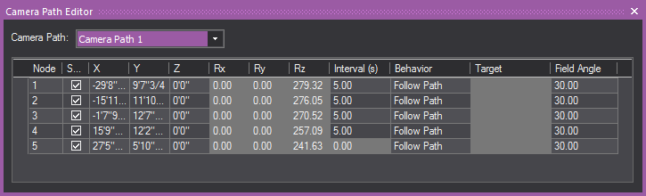
Camera path editor columns
- Node: This column gives
you the Node number of the nodes on your Timeline.
- Shortest Path: When
the Shortest Path checkbox is selected
for a node, it forces the camera to rotate as little as possible when
moving between two nodes on your timeline. When the Shortest
Path checkbox is cleared for a node, the camera will take
the longer of the two directions as it rotates to aim at the next
node's target. This applies to Roll, Pitch and Yaw.
- X,
Y, and
Z Columns: The
X, Y, and Z columns in the Camera Path Editor
are editable position information for each of the nodes on your timeline.
You may enter in distance values into these fields to re-position
your nodes as you see fit.
- Rx
and Rz
Columns: These
columns represent the rotation around each of the X and Z axes in
Vivien. These columns are non-editable, but allow you to get positional
information from your nodes.
- Rx, or
Rotation around the X Axis = PITCH [tilting
forward and backward]
- Rz, or
Rotation around the Z Axis = YAW [also
called Heading or Direction]
- Interval: A node’s Interval
is how long it takes in seconds to get from one node to another. For
example, if the timing on node 2 is ten seconds (10s), then the camera
would move for ten seconds before reaching node 2.
- Behavior: Behavior is the
camera’s movement and direction behavior as it relates to the Camera
Path. There are three types of Camera Behavior:
- Follow Path: The
camera will follow straight along the path, not deviating in any way
possible from the path as it travels between nodes.
- Follow Target: The
camera will always point at an assigned Camera Target if this behavior
is chosen for a node.
- User Defined: This
option allows the camera to behave exactly as specified by a user,
meaning that the camera will point wherever you point it when the
User Defined behavior is chosen.
- Target: Each
node can be assigned a different target when the Follow Target behavior
in the Behavior column is chosen. The Target column is a drop-down
box for choosing different targets in your drawing.
- Field Angle: This
option allows you to enter in different field angles for each node.
To
use the Camera path editor
- In Lighting Wireframe / Quad or Virtual View,
from the menu, choose .
- In the Camera Path Editor,
from the Camera Path drop-down list,
select the Camera path that you want to edit.
- In the Interval column,
adjust the timing for each node along the path, specifying when you
want the camera to be at that node.
- If you have placed targets along the path, and
you want the Camera to follow a target at a particular node, in the
Target column click in the cell corresponding
to the node and, from the drop-down list that appears, select Follow Target. Then, click in the adjacent Target
cell to select the target.
- To define the orientation and field angle of
the Camera at a particular node along the path, in the Camera
Target column, click in the cell corresponding the node, and
then select User Defined.
- Once you have defined the time intervals, you
can use the Timeline tool to watch
the Camera path play in the Virtual View. For details, see below.
Visual
Camera Path Builder tool
The Visual Camera
Path Builder tool allows you to create a Camera Path on the
fly while you move the Camera around your space. This tool essentially
works by placing a node at the Camera’s current position once you’ve told
Vivien that you are satisfied with the Camera’s current placement on screen.
Note: The Visual Camera Path
Builder tool is disabled if the
Virtual View Camera Control was set to
Other 3D Applications in the General tab
of the Application Options window.
To use the Visual Camera Path Builder tool
- Right-click in the Virtual View and select .
- Once you’ve started the Visual
Camera Path Builder, you’ll be prompted to name your new path,
add it to the Camera layer (or a layer of your choosing), and create
the first node based on the Camera’s current position.
- Once you click OK in
the dialog box, you will then be in Visual Camera Path Editor mode.
Maneuver the Camera around the space, and when you want to create
a new node based on your Camera’s position, right-click in the Virtual
View and choose the Add Node. At this
point, you can also Abort your Camera Path in the Visual
Camera Path Builder tool.
- Move the Camera and right-click every time you
would like to create a new node from your Camera’s current position
in space.
- When you have created as many nodes as you would
like to have in your Camera path, right-click again in the Virtual
View and choose .
- At this point, you can also Abort your Camera
Path, or you can choose to Close the Camera path from your current
view, which will create a seamless loop on the Camera path. When you
are finished with the Visual Camera Path Builder tool, you will automatically
exit the Visual Camera Path Builder tool mode.
To
use the Timeline tool
Once you have adjusted the timing of a
Camera path with the Camera path editor, switch to the Virtual View to
watch the camera move along the path with the Timeline tool.
This tool enables you to watch the timing in slow motion, regular speed,
or up to four times the speed.
Notes:
- Camera Path playback is also simulated in Full
Screen mode.
- Nodes of existing Camera Paths can be edited
from a Virtual View when the Timeline's Previous Node or Next Node
buttons are used; they can only be edited while playback is paused.
- In Lighting Wireframe / Quad or Virtual View,
from the menu, choose .
Result: The Timeline tool
appears.

- Use the controls to watch the Camera move along
the path you have defined:
- Play: Click to start
the camera path simulation in the Virtual View. While this plays,
the red line moves along the timeline to display its current position.
You can click on the red line indicator and scrub along the timeline,
which updates the red line and the Camera simulation at the corresponding
point along the path.
- Stop: Click to stop
the camera.
- Previous Node: Click
to switch back to the previous node on the path.
- Next Node: Click
to move to the next node on the path.
- Toggle PlayBack Direction:
Click to switch the direction of the camera on the path.
- Toggle Loop: Click
to keep the camera moving on the path in a continuous loop.
- Adjust Playback Speed:
Click to choose the playback speed.
- Show Node Numbers:
Click to show the node numbers in the timeline.
- Zoom: Use the slider
to zoom in or out on the timeline.
Using the Camera Manager
The Camera Manager enables
you to view and set the properties of Camera objects and Camera Paths
in a convenient way. The Camera Manager window opens in the wireframe and virtual
views, and displays the following:
- The editable settings for New
Camera Defaults showing Layer,
Field Angle, and Aspect
Ratio.
- The option to Override all
Cameras’ Aspect Ratio checkbox.
- The table with the list of Camera objects inserted
in the plot and their settings: Camera Name,
Lock, Hotkey,
Field Angle, Aspect
Ratio, and DMX Value.
- The table with the list of Camera Paths created
in the plot and their settings: Camera Path Name,
Show Path, Node,
Node Number, Aspect
Ratio, DMX Patch.
To access the Camera Manager
- From the menu,
choose .
Result: The Camera Manager
window appears.
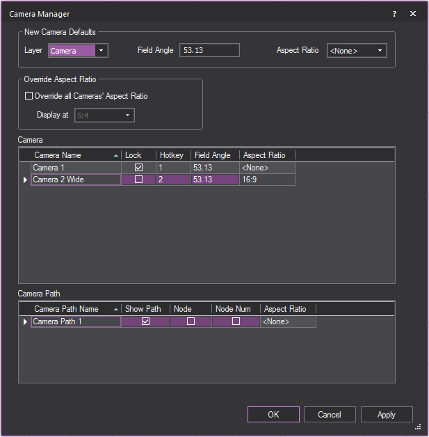
To edit Camera and Camera Path properties in Camera Manager
- In the Camera Manager window,
you can change any of the following properties:
New Camera Defaults
This section shows the default properties
set for a new camera object that will be inserted in the drawing.
- Layer: you can select
the default layer of the new camera object.
- Field Angle: you
can specify the default field angle (degrees) of the new camera object.
- Aspect Ratio: you
can select the default aspect ratio of the new camera object.
Override Aspect Ratio
This section shows the option to change
the Aspect Ratios for all Cameras.
- Override all Camera’s Aspect
Ratio - Display at: Select this checkbox to override the
aspect ratios for all cameras and select a temporary aspect ratio
from the drop-down menu to view all cameras in your drawing.
Note: All previously set Aspect Ratios are preserved
in the table, and can be used after this option is disabled.
Camera
This section shows the list of camera objects
inserted in the plot with their corresponding properties.
- Camera Name: Click
the Camera Name cell to edit the camera’s name.
- Lock: Select this
checkbox to lock the selected camera in the Virtual View.
- Hotkey: Click this
drop-down menu to assign a new numbered hotkey for the selected camera.
- Field Angle: Click
the Field Angle cell and write the new field angle (degrees) for the
selected camera.
- Aspect Ratio: Click
the drop-down menu to select a new fixed aspect ratio for the selected
camera. This option is disabled when Override
all Cameras’ Aspect Ratio is checked.
Camera Path
This section displays the list of camera
paths created in the plot.
- Camera Path Name:
Click the Camera Path Name cell to edit the camera path’s name.
- Show Path: Select
this checkbox to show the selected Camera Path.
- Node: Select this
checkbox to show the nodes created along the selected Camera Path.
- Node Num: Select
this checkbox to show the numbers assigned to each of the nodes along
the selected camera path.
- Aspect Ratio: Click
the drop-down menu to select a new fixed aspect ratio for the selected
camera path.
Drawing a compass
Add a compass to your drawing to define
the direction that is north. This definition is important to set the position
of the sun and/or moon for renderings that use environmental options.
There can be only one compass in a file.
To draw a compass
- From the menu,
choose .
- Click to place the starting point of the compass.
- Click to place the end point of the compass. The
end point must be directly north of the start point.
Result: A compass displays, centered on the start
point and pointing towards the end point.
- To remove the compass from the drawing, choose
from the
menu.
- To redefine north, repeat steps
1-3. You do not need to remove the compass from the drawing
when redefining as there can be only one compass in a file.
Drawing
pipe and drape
Use Vivien’s Pipe
and Drape Wizard to add lengths of drapery to your drawing.
You can quickly add the default length and height of drapery, or specify
custom sizes and define drapery properties such as color, texture, and
material in the wizard or after inserting the drapery in your drawing.
Vivien’s Event Resources tab keeps track
of the number of drape panels, crossbars, and upright pipes you will need
to ensure that your equipment quotes are accurate.
The several components in a drape line
are shown in the following graphic:
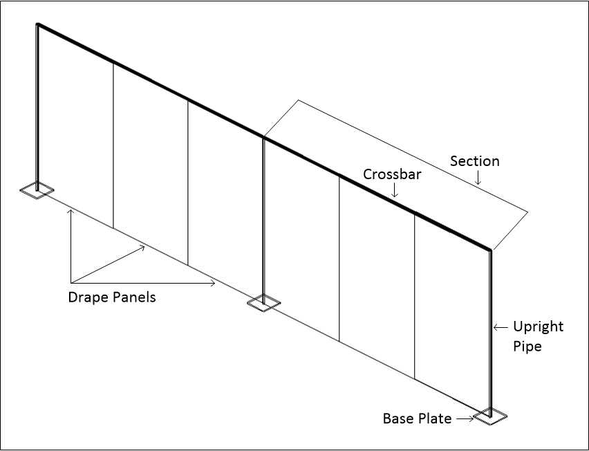
- Drape panels:
These are the individual pieces of fabric that hang from the horizontal
pieces of pipe called crossbars. You can specify the number of drape
panels in each of the pipe and drape drawing methods. The default
number of panels is three per section.
- Section:
A section consists of a series of drape panels hanging from a horizontal
pipe called a crossbar, which is supported on each end by an upright
pipe. You can specify the number of panels per section and, based
on the drawing method you choose, either the exact width
of the section or the maximum
width.
- Upright pipes:
These are the pipes that stand on either end of each section in your
drape line, supporting the crossbars.
- Base
plates: These are the support plates for the upright pipes.
The Pipe and Drape
Wizard offers you two drawing options:
- Draw: This is the
most flexible option when drawing your drape line. It enables you
to specify the height, maximum width of a section, and the number
of drape panels per section. When you click Finish,
the Wizard returns you to the drawing where you can click and drag
to draw as many drape lines as desired in whatever length required.
- Specify: This option
enables you to define the height, width, the number of sections in
your drape line, and the number of drape panels per section. This
option enables you to either draw a new drape
line section, or add to an existing
drape line.
To
draw pipe and drape - Draw method
Note: If you are adding a new drape section to an
existing panel in your drawing, click the Endpoint
snap tool first. This ensures that the new drape panel “snaps”
to the existing one in the correct position.
 The
Endpoint snap button.
The
Endpoint snap button.
- On the toolbar, click the Pipe
and Drape Wizard tool.
 The
Pipe and Drape Wizard button.
The
Pipe and Drape Wizard button.
Result: The Select Drawing Method
window appears.

- Select the Draw option
button, and then click Next.
Result: The Draw Pipe and Drape window
appears.
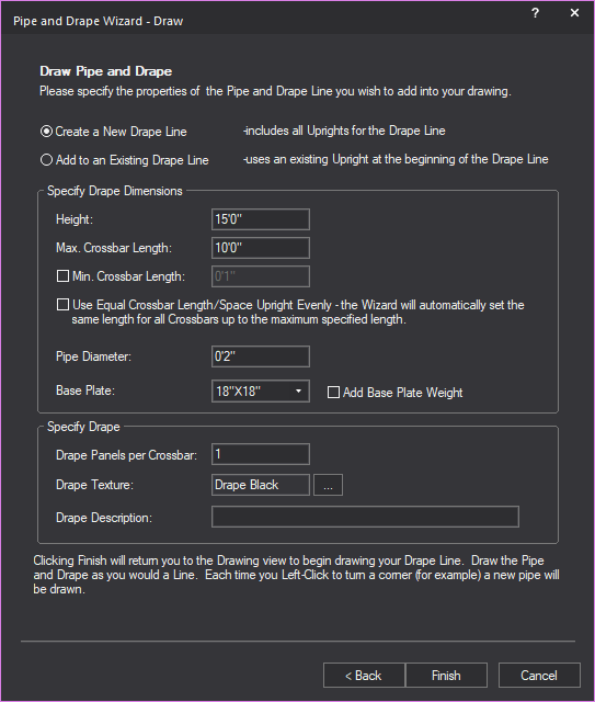
- Select the Create a New Drape
Line option to create a new section of the drape line;
or select the Add to an Existing Drape Line option
to add the next section of the drape line.
Notes:
- Drawing a new drape line includes all upright
pipes for the drape line.
- Adding to an existing drape line uses an existing
upright pipe as the beginning of the added drape line.
- In the Height box,
type the height of the drape line, or accept the default value of
15’0”.
- In the Max. Crossbar Length box, type the maximum
length of each horizontal pipe, or accept the default value
of 10’0”. This is the length of the horizontal pipe between the upright
pipes. If you click to insert a section at a shorter interval than
this value, Vivien automatically adjusts the width of each drapery
panel accordingly and a shorter section is inserted in the drawing.
- Select the Min. Crossbar
Length checkbox and type the minimum length of each horizontal
pipe, or accept the default value of 1”. This value sets the shortest
length of the horizontal pipe in a section between upright pipes.
- Select the Use Equal Crossbar
Length/Space Upright Evenly checkbox to automatically
set the same length for all the crossbars. If you clear this checkbox,
then Vivien creates the drapery panels of equal size for all full
sections, but resizes the panels in the last section accordingly if
you choose to make this panel smaller.
- In the Pipe Diameter box,
type the diameter of all crossbars and upright pipes.
- Click the Base Plate drop-down
to select the size of the base plate support for the upright pipes.
- Select the Add Base Plate
Weight checkbox to add thickness to the base plate in
Wireframe and Virtual Views.
- In the Drape Panels per Crossbar box,
type the number of drape panels that you want to see in each section
of the drape line, or accept the default value of 3 panels per section.
Each panel is separated by a new, upright piece of pipe.
- The default or previously set texture of the drape
is displayed in the Drape Texture box.
To change the texture, click the Drape Texture ellipsis
button to browse and select a new texture from the Texture
Select dialog box that opens.
- In the Drape Description box,
type additional user information or identification for the drape line,
which will be displayed in Reports.
- Click Finish.
- Click in the desired spot in your drawing where
you want to start drawing the drape line.
- Move the cursor to the spot where you want the
first section to end, and click. Then move your cursor to the spot
where you want the next section to end, and click. You can draw as
many sections as you like. When you are finished drawing your drape
line, right-click and select Finish Pipe and
Drape.
For details on customizing the new drape
line, see “To
customize drapery elements (color, material, and texture)”.
To draw pipe and drape
- Specify method
Note: If you are adding a new drape section to an
existing panel in your drawing, click the Endpoint
snap tool first. This ensures that the new drape panel “snaps”
to the existing one in the correct position.
 The Endpoint snap button.
- On the toolbar, click the
Pipe and Drape Wizard tool.
 The
Pipe and Drape Wizard
button.
The
Pipe and Drape Wizard
button.
Result: The Select Drawing Method
window appears.
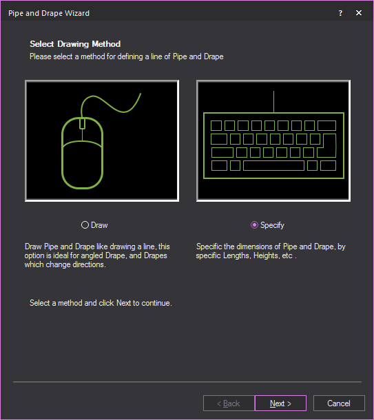
- Select the Specify option
button, and then click Next.
Result: The Specify Pipe and
Drape window appears.
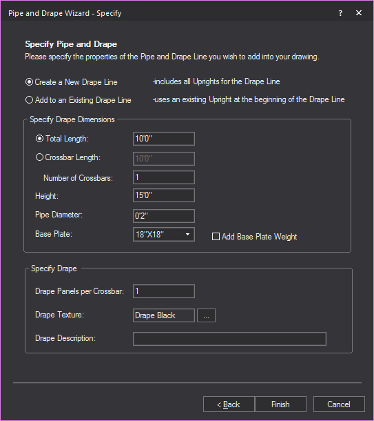
- Select the Create a New Drape
Line option to create a new section of the drape line;
or select the Add to an Existing Drape Line option
to add the next section of the drape line.
Notes:
- Drawing a new drape line includes all upright
pipes for the drape line.
- Adding to an existing drape line uses an existing
upright pipe as the beginning of the added drape line.
- To specify the total length of the drape line
section, select Total Length and
type the length of the drape line, or accept the default value of
10’0”. The Crossbar Length option
is disabled if the Total Length option
is selected.
- To specify drape line section by the length and
quantity of it’s crossbars, select Crossbar Length and
type the length of the crossbar, or accept the default value of 10’0”
The Total Length option is disabled
if the Crossbar Length option is selected.
- In the Number of Crossbars box,
type the number of crossbars in the drape line, or accept the default
value of 1.
Note: The length of each crossbar will automatically
change with reference to the specified Total Length and
Number of Crossbars.
- In the Height box,
type the height of the drape line, or accept the default value of
15’0”.
- In the Pipe Diameter box,
type the diameter of all crossbars and upright pipes.
- Click the Base Plate drop-down
list to select the size of the base plate support for the upright
pipes.
- Select the Add Base Plate
Weight checkbox to add thickness to the base plate in
Wireframe and Virtual Views.
- In the Drape Panels per Crossbar box, type the number of drape panels that
you want to see in each section of the drape line, or accept the default
value of 3 panels per section. Each panel is separated by a new, upright
piece of pipe.
- The default or previously set texture of the drape
is displayed in the Drape Texture box.
To change the texture, click the Drape Texture ellipsis
button to browse and select a new texture from the Texture
Select dialog box that opens.
- In the Drape Description box,
type additional user information or identification for the drape line,
which will be displayed in Reports.
- Click Finish.
- Click in the desired spot in your drawing where
you want to start drawing the drape line.
- Move the cursor to the spot where you want the
first section to end, and click. Then move your cursor to the spot
where you want the next section to end, and click. You can draw as
many sections as you like. When you are finished drawing your drape
line, right-click and select .
For details on customizing the new drape
line, see “To
customize drapery elements (color, material, and texture)”
below.
To
quickly change Pipe and Drape Wizard settings
This procedure shows you how to quickly
change some of the structural pipe and drape settings for a selected drape
line, such as the height and diameter of the upright pipes and crossbars.
Use this procedure to customize the structural properties of a
single drape line.
- In your drawing, select the pipe and drape sections
that you want to customize.
Tip: To select multiple sections, press CTRL,
and then click the appropriate sections.
Note: The sections that you select must have been
drawn in the same way. For example, all drape lines created with Specify
method.
- Right-click and select .
Result: The appropriate Settings window appears. Based
on the type of drape line that you selected, a different window appears.
- Change any of the settings that you see in this
window. For help on any of the boxes, click in the box, and then press
F1.
- Click Finish to save
and apply your new settings.
To customize drapery elements
(color, material, and texture)
You can add custom color, texture and material
to selected drapery elements (such as the front and back of the drape
panels, the crossbars, upright pipes, the drape loops that attach to the
crossbars, or the drape lines as a whole).
Notes:
- If you select multiple drape lines in your drawing,
you can apply the same properties to all of them simultaneously through
the following procedure. However, if you had already selected varying
properties (for example, if you had chosen one color for the front
panel of some drape lines, but another color for the front panel of
others), or if some of the elements had no properties selected at
all, then when you choose new properties in the following procedure,
it applies to all drape
lines selected, overwriting any existing settings that you may have
saved.
- When you select multiple drape lines, the Appearance tab only lists the properties
of selected elements if they are common across all drape
lines. For example, if the front panel of all selected drape lines
already has the same custom texture applied, and it is set to tile
in one meter squared intervals, then these values are shown in the
Appearance tab. However, if at least
one of the front panels in the selected drape lines has a different
custom texture value applied, the Appearance tab
does not list the texture settings at all. If you choose new texture
settings, your choice overwrites all existing settings for the selected
element across all selected drape lines.
- You can apply the same properties to all drapery
elements by highlighting “Group” in the Elements box.
- In your drawing, select the pipe and drape sections
that you want to customize.
Tip: To select multiple sections, press CTRL,
and then click the appropriate sections.
- With the desired sections selected, right-click
and select .
Result: The Properties
window appears.
- Click the Appearance
tab.
- In the left pane, click the drapery element that
you want to customize. For example, to customize the front of the
drape panels (each panel is double-sided), click Drape
Front.
Note: You can select multiple elements by pressing
CTRL, and then clicking the elements; you
can select all elements
by clicking Select All.
- You have a choice of applying one of
the following settings to the selected elements:
- Layer Rendering Color:
Select this option to apply the same color as the current layer to
the selected elements.
- Custom Color: To
apply a custom color, select this option, and then click
the color box. In the resulting color dialog, select the custom color
that you want to use, or click Define Custom
Colors to create your own color. Click OK,
and then click Apply.
- Texture from Library:
Select this option to apply a custom texture file from the Vivien
library to the selected elements, and then click the ellipsis button
(...). In the resulting dialog, navigate to and highlight the desired
texture. Click Select.
- Image Source: To apply a custom texture file that you
have created and saved in bitmap or jpeg format, select this option,
and then click the ellipsis button (...). Navigate to the file, and
click Open.
- Use Normal Map: Select
this checkbox to apply an Image Source that’s a Normal Map, to create
the perception of fragmented surface texture detail and depth, making
objects look more realistic.
Click this drop-down box to apply an existing
Normal Map image or click New to create
a new Normal Map image via the Image Manager.
Note: This
drop-down lists all Image Sources that appear in the Image
Manager; as such, Image Sources which are Normal Maps should be
named appropriately for easy identification.
- Scale: Select the
height or depth of visual effect created by the Normal Map. Click
the drop-down box to select the percentage scale value from not visible
(0%) to maximum value stored in the imported Normal texture/image
(100%).
- If you have chosen to apply a texture to the elements,
you can choose how the texture will appear on the selected drapery
elements as follows (if you have applied a color instead, you can
skip directly to step 7):
- To view the texture file as a series of square
or rectangular “tiles” that are repeated over the entire surface of
the drapery element, click the Tile option
button, and then type the size of the tiles in the boxes provided.
- To view the texture file stretched out as a single
surface over the entire drapery element, click the Stretch
option button.
- To preserve the aspect ratio of the texture so
it is not distorted when stretched over the element, click Keep
Aspect Ratio.
- To choose a custom border color for the texture
when it is stretched over the surface of the element, click the Border Color box, and then choose the custom
color.
- If you have selected Use
Normal Map, specify the number of times the Normal Map is multiplied
across the object (element) to which it is applied. Type the value
in the Normal Map Size Multiplier box.
(Enter a valid number between 0.01 and 100.)
Notes:
- The default value of 1 results in no changes
to the Normal Map’s size; values lower than 1 will increase the
size of the Normal visual effect, and values higher than 1 will
decrease it.
- The Normal Map Size
Multiplier operates within
the Tile or Stretch Texture
Options.
- To set the angle at which the texture appears
on the drapery element, type the value in degrees in the Rotation
(Deg.) drop-down list.
- To change the color of the texture, click the
Color Tint color box and select a
new color, then click the Scale drop-down
list to specify the intensity of the color.
- To choose a custom material for the selected drapery
elements (such as metal, paper, plastic, or fabric) click the ellipsis
button (...) in the Material Properties
section.
- In the resulting dialog box, navigate to and highlight
the desired material, and then click Select.
- Click Apply.
- If desired, you can apply a transparency level
to the selected element. Based on the settings that you have chosen
for color, texture, and material, the transparency options vary as
follows:
- Transparency: This
setting controls the proportion of light that passes through the material.
All materials in Vivien specify a level of transparency that varies
from one material to the next. For example, glass is more transparent
than brick. If you select Default, the
transparency level is set to 0% (opaque).
- Specular Level: This
setting controls how prominent other specular effects appear on the
material.
- Specular Gloss: This
setting controls the amount of light that is projected on the material.
- Specular Color Source:
This setting controls the amount of light that is projected on the
material.
- Light Reflection:
This setting controls the amount of light that is reflected off the
material.
Notes:
- Use the drop-down menus to change any of the
material properties. Use the Reset button
to revert back to defaults.
- The beam will pass through a surface with the
Transparency value set to 80% or greater. The beam will not pass through
the surface when the value is lower than 80%.
- Display Reflection in Virtual
Views: Select this checkbox to display the set reflective characteristics
in Virtual Views.
- Click Apply.
- Click OK to save
your changes and close the Properties
window.
To customize pipe
and drape structure for individual drape lines
This procedure shows you how to customize
other properties of the pipe and drape sections, such as the height and
diameter of the upright pipes and crossbars. Use this procedure to customize
the structural properties of individual
drape lines that you have selected.
Note: While the tabs in the Properties window
are best used to customize a single drape
line, if you selected multiple drape lines, the values that you type in
these tabs apply to all selected
drape lines; they overwrite any custom settings that you previously saved
for individual crossbars, uprights, or drape panels.
- In your drawing, select the pipe and drape section
that you want to customize.
- With the desired section selected, right-click
and select .
Result: The Properties
window appears.
- To change any properties of the drape line crossbars,
click the Pipe and Drape
tab.
Pipe:
This section displays the properties of the drape
line crossbars and upright pipes.
- Crossbar section:
- Length: Type
the length of all crossbar pipes in the selected drape line.
- Diameter: Type
the diameter of all crossbar pipes in the selected drape line.
Updating the crossbar diameter will update the loop diameter.
- Upright section:
- Height: Type
the height of all upright pipes in the selected drape line.
- Diameter: Type
the diameter of all upright pipes in the selected drape line.
Changing the upright height will update the drape height.
- Base Plate: Click
the Base Plate drop-down list
to select the size of the base plate support for the upright pipes.
- Add Base Plate Weight:
Select this checkbox to add thickness to the base plate in Wireframe
and Virtual Views.
- Use Document Defaults (Segments):
Clear this checkbox if you want to specify the number of segments
that comprise the circumference of the crossbar pipes. You can choose
between three and 40 segments. This value is largely for rendering
purposes—the greater the number of segments, the greater the rendering
time. Leave this checkbox checked to accept the default value of 8
segments.
Drape
This section displays the properties of
the drape line panels.
- Panel
section:
- Height: Type
the height of all panels in the selected drape line.
- Width: Type the
width of all panels in the selected drape line.
- Loop Diameter:
Type the diameter of the loops that wrap around the crossbar pipes
at the top of all panels in the selected drape line. This value
should be greater than the diameter of the crossbar pipes.
- Use Document Defaults
(Segments): Clear this checkbox if you want to specify
the number of segments that comprise the drape panel loop that
wraps around the crossbar pipe. You can choose between three and
40 segments. This value is largely for rendering purposes—the
greater the number of segments, the greater the rendering time.
Leave this checkbox checked to accept the default value of 8 segments.
- Curtain section:
- Enable: Select
this checkbox to display the curtain as a wave in Plan View.
- Curtain Folds (2D Plan
Only):
- Style: Choose
the style of how the wave is displayed.
- Depth: Type
the depth of each wave period.
- Width (Period):
Type the width of each wave period.
- Number of Segments:
Type the number of segments for the 2D wave object.
- Click Apply.
- Click OK.
Result: Your
changes are applied to all selected drape lines.
Mirroring
pipes
Once a pipe is created, a mirror image
of the pipe can be created. Mirroring duplicates and reverses the pipe,
inserting it the same distance from an axis line as the original pipe.
Both straight and curved pipes can be mirrored. A mirrored pipe will also
include any fixtures attached to the original pipe, but aiming the fixtures
at the new mirrored angle. “Mirroring
objects” for more information.

Mirroring
truss
Once a truss is created, a mirror image
of the truss can be created. Mirroring duplicates and reverses the truss,
inserting it the same distance from an axis line as the original truss.
Both linear and circular trusses can be mirrored. A mirrored truss will
also include any fixtures attached to the original truss, but aiming the
fixtures at the new mirrored angle. “Mirroring
objects” for more information.