
Library truss differs from the truss created using the Truss Wizard in that structures are built from multiple pieces, which have real life equivalents. You may use these pieces (found in the Library Browser's AV tab > Truss folder) to build more complex and realistic truss structures than the Truss Wizard can create.
When inserting or having selected truss pieces from the Library, a 3D indicator appears, displaying a directional/positional reference for the individual piece of truss. You can use these indicators as a visual guide, helping you to assemble truss structures and instantly determine if a truss structure was not assembled as intended.
Notes:
Indicators are visible whenever you select truss or when you are in the process of assembling/inserting it. When you are snapping a new piece of truss to an existing piece, if you see that the indicator for the existing piece does not align with the indicator for the new piece, right-click and select a different mount point, or roll the truss as necessary (rolling truss may be required on rare occasions when triangular truss or corner blocks are used), to ensure that the two indicators align.
Naturally, corner blocks and connectors have to be taken into consideration. For example, in the truss structure shown below (starting from the bottom left-most section and traversing counter-clockwise), the two truss pieces along the bottom have matching indicators.
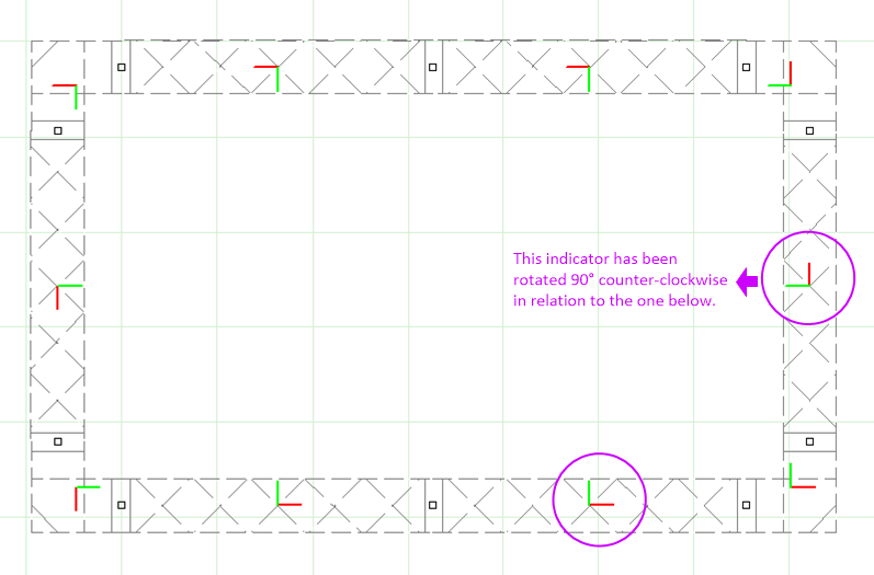
When the 90º corner block is used, the “running direction” of the truss changes. As such, the next truss piece is now rotated as shown by its indicator. This continues all the way around this rectangular truss structure until we connect back to the bottom left corner.
As the example demonstrates, while not all indicators will align in the same orientation (which would be impossible), the assembly may still be correct. When creating truss structures, take a moment at each corner block to analyze how the running direction of the truss changes due to the corner block. To do so, look at the indicator alone and visualize what would happen if you rotated it by 90º (or another angle, depending on what corner block/connector you are using).
If the indicator of the existing piece had the red line pointing to your right and green pointing up, rotating it 90º counter-clockwise would cause the green line to point to your left and the red to point up, while rotating the indicator 90º clockwise would cause the green line to point right and the red arrow to point down.
These are the only two cases in which fixtures hanging from the two pieces attached to the 90º corner block would behave “as expected”; should the indicators appear in any other orientations, undo and assemble the truss again, making sure not to activate any of the right-click roll/alternate mountpoint options as you begin the assembly.
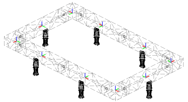
As you can see from the isometric screenshot of this same truss structure (below), all of the blue indicators are pointing in the same direction, which means that all lights hung from this truss will point downwards to the floor.
Before you start inserting truss to create truss structures, ensure that the following options are enabled (they are by default):
In addition, ensure that the Height at which the truss is to hang has been set.
The "Ladder" is the side of a truss that can be climbed; the four orientations listed here indicate orientation in screen space when working in Top (Plan) view: 0° will insert the truss vertically with the ladder side at the right, 90° at the top, 180° at the left, and 270° at the bottom.
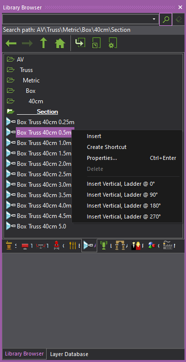
Result: A piece of truss attaches to the cursor.
Note: To change the truss type (in most cases to another piece from the same category), return to the library, double-click on the name of the new desired truss type and continue placing truss pieces as normal.
Tip: You can also use Truss shortcuts.
Refer to Working_with shortcuts.
Assembly Snap assembles truss pieces together ensuring proper structural assembly. As with all snap functions, you can click Assembly Snap in mid-command or as a running snap type.
Enable Assembly Snap before inserting truss to assemble and group all subsequently inserted pieces of truss. (This option is enabled by default in all new files.)
Enable Assembly Snap after inserting the first piece of truss to assemble selectively. Assembly Snap disengages after you place the next piece of truss, assembling only the first truss (or group of trusses) with the second piece.
Result: The new piece is assembled to the old piece; once insertion is complete, the inserted pieces are automatically grouped if the Automatically group truss option is enabled.
The following video demonstrates this technique:
Result: The new truss piece inserts, assembled to the existing piece or structure.
Sometimes while building truss, you will notice that a mistake was made. It is easy to fix mistakes right away if noticed immediately, but sometimes these things are noticed much later after the truss structure was already built. (In addition, occasionally, the truss structure itself needs to be changed as a result of structural issues, hardware availability, etc.)
It is possible to ungroup the assembled truss structure, make edits, and then if the truss objects are positioned so they can be reassembled, select them all and reassemble them easily.
Result: The truss structure is reassembled as if it was built like this originally, and features like Fixture Array or Fixture Distribution along a section of Truss will work.
The following video demonstrates Truss Reassembly:
Note: After the selected truss is reassembled, it is grouped automatically.
A Mountpoint is any part of a truss section or corner block to which another section or corner block can be attached.
The Select Mountpoint options are only available (in the right-click menu) while truss is being attached to an existing piece. Their purpose is to allow a different Mountpoint of the truss to be selected during assembly.
Selecting a different Mountpoint is sometimes necessary when you are attaching a connector or corner block to a straight or curved section of truss, in case attaching with the default Mountpoint is not desired or would result in an incorrect structure.
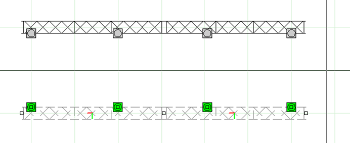
Selecting a different Mountpoint is always necessary when you are assembling straight or curved truss section runs from the center out. For example, if you were to build the truss structure starting at the center line and first inserting pieces towards the right, and then attaching sections from the center towards the left, you would need to change to Mount 2 once you start to attach sections towards the left; otherwise, the Truss Indicators would show you that the running direction of the truss is no longer correct.
The following video demonstrates the use of Mount Points:
Note: The selected Mountpoint is maintained until a new piece of truss is selected for insertion. This is to facilitate building truss structures in the fashion described above (i.e., starting at the center and building towards the right, and then coming back to center and building towards the left).
When inserting Triangular truss pieces, on extremely rare occasions, you may find that their chords don't line up. In such cases, much like when selecting alternate Mount points, you may right-click (once the piece has jumped off the cursor) to roll the piece along its long axis in 90 degree increments, until the correct orientation is reached - then click to insert the piece in that orientation.
Once a straight or curved truss is created, a mirror image of the truss can be created. Mirroring duplicates and reverses the truss, inserting it the same distance from the mirror line as the original truss. Both linear and circular trusses can be mirrored. A mirrored truss will also include any fixtures attached to the original truss.
![]() © The CAST Group of Companies
Inc., 2004-2022 All rights reserved.
© The CAST Group of Companies
Inc., 2004-2022 All rights reserved.