
Using the Video Manager
The Video Manager enables you to bring a live
or pre-recorded video into Vivien and play it back. To do so, you create
video sources, which you can then assign to screens and to projectors
that you have inserted in your file from the Library
Browser. For detailed information on drawing screens, see “Drawing
screens”.
Notes:
- To play the video, you use the Video Tool. For more information, see “Using
the Video Tool”. You can view the video in any of the Virtual
Views, using the controls on the Video Tool
to pause, fast forward, rewind, or stop the video.
- Before you render your drawing, you can either
pause the video at the precise image you want to see in the final
rendering, or you can let the video run while the Render
Wizard processes the information in your drawing. In this
case, the Render Wizard captures
the video frame that was showing when it processed the screen information.
- The Video Manager window
can be resized to accommodate videos that have a higher or wider aspect
then the default window size.
To access the video manager
From the .
Result: The Video Manager
appears.
Video sources
- Video File is
a pre-recorded video saved in your computer in a specified video file
format. Vivien supports video files in the following formats:
- MPEG-4 “.mp4”
- MPEG-2 “.mpg”
- Matroska “.mkv”
- Windows Media Video “.wmv”
- Audio Video Interleave (AVI) “.avi”
- QuickTime File Format (QTFF) “.mov”
Note: If you cannot view these file types, you may
not have the proper CODEC installed on your PC. Install the appropriate
CODEC, and then try viewing the file again. For more information about
playing back video files and the use of CODECs, please see https://forums.cast-soft.com/index.php?threads/playing-video-files-in-vivien.1172/.
- Video Capture is
a live video stream that comes from an external video capture device
or a Blackmagic Design Device.
- Camera (I-Mag) is
a Video Source that displays the view from Cameras drawn in Vivien
when applied to the Screens, Video Projectors, and LED Walls.
Video subsources
Video Sources can be split into subsources
in the Video Manager. This enables you to
apply portions of the video to multiple screens, 3D primitives, LED Walls,
or projectors. For more information on creating Video subsources, see
“Splitting
video into subsources”.
To create a new
video source in the video manager
- In the Video Manager,
click the New icon.
Result: The Video Source
window appears.
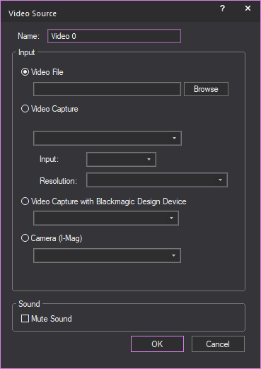
- In the Name box, type
the name of the Video Source.
- Select the Video Source from the options in the
Input section.
Note: When a Blackmagic Design video capture device
is detected, the Video Capture with Blackmagic Design
Device radio button is automatically selected. In order for
these devices to work properly, always use this option, not the Video Capture option above it. To connect
them, their input source and resolution are selected through the utility
that was installed with their driver.
- Camera (I-Mag): The
view from the camera drawn in Vivien.
- Browse to locate the video on your computer, and
then click OK.
Result: The video is added as a source.
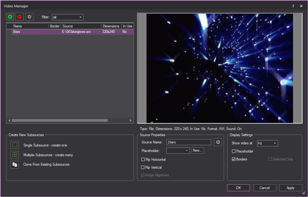
- Name: The video’s
file name.
- Source: The path to
the physical file.
- Dimensions: The file’s
dimensions in pixels.
- In Use: Informs you
of whether the video source is in use. If the video source is currently
in use, it cannot be deleted from the Video Manager.
- Mute: Indicates if
the sound has been muted in the video.
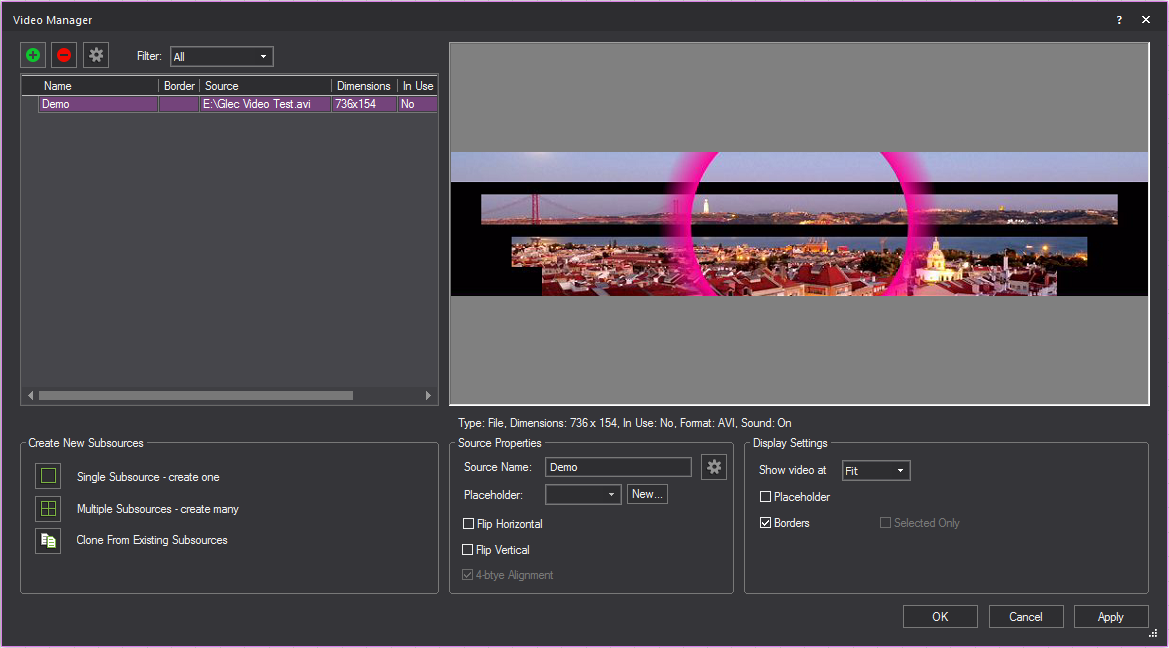
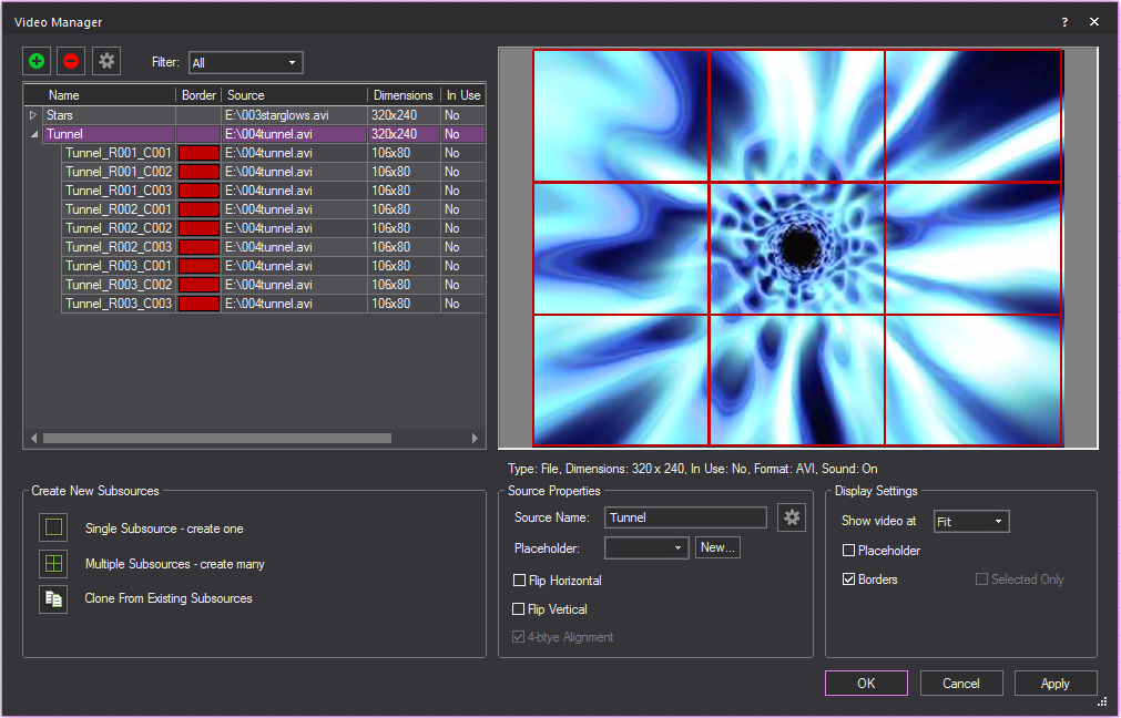
Display Settings
- Show video at: Select
the zoom level for the video. You can choose to Fit the
video in the display window, or show it at a percentage of its actual
size: 100%, 200% or
300%.
- Placeholder: Select
this options to display the placeholder that was set in the Source Properties section.
- Borders: Select this
option to show the subsource borders in the display.
- Selected Only: When
you have selected a subsource in the table, select this checkbox to
only show the subsource in the display area; if you do not select
this checkbox when a subsource is selected, the entire source is shown
(with the subsource borders highlighted in the display if you selected
Borders).
Source Properties
- Source Name: The
video file’s name.
- Placeholder: Select
the image file that was created in Image Manager,
or click New to create a new placeholder
image in Image Manager.
- Flip Horizontal:
Select this option to flip the video source.
- Flip Vertical: Select
this option to flip the video source vertically.
- 4-byte Alignment:
Select this option to align the pixels of a distorted video image.
The 4-byte Alignment checkbox is
automatically available only if the video source requires the alignment.
For details on using the Video
Tool to play the video, see “Using
the Video Tool”.
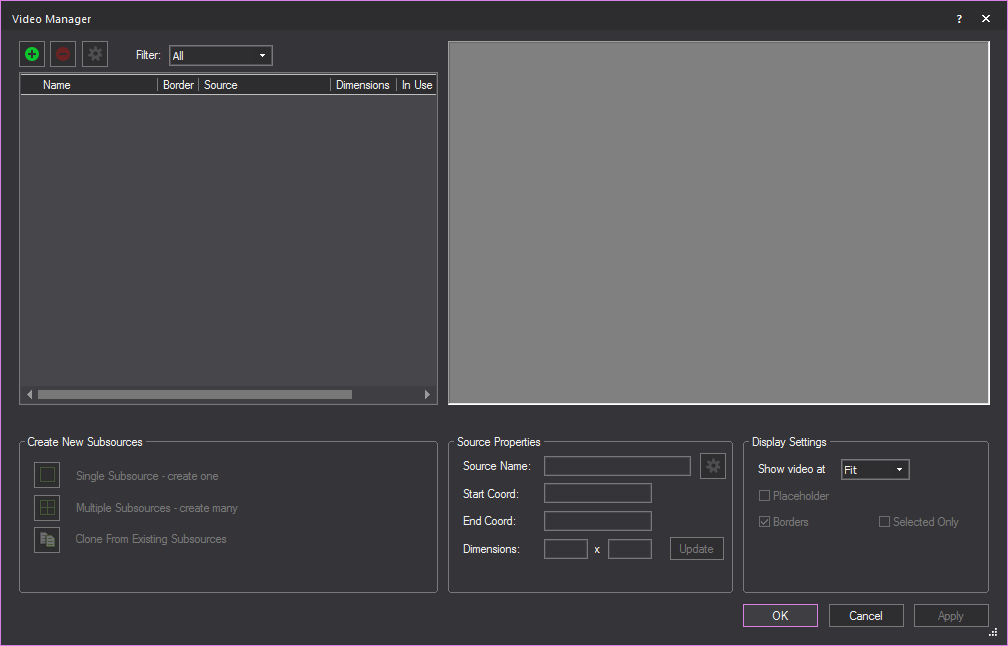
Splitting
video into subsources
After you setup the video source in the
Video Manager, you can take the video source
and split it up into subsources that you can apply to multiple screens,
3D primitives, or projector-style fixtures that you have inserted from
the Video Projection section of the Fixtures library.
To do so, click the Split
Video tab in the Video Manager,
select a video source that you set up, and then split it either manually
(by defining the pixel coordinates of each split) or automatically/evenly
(by setting the number of rows and columns). You can then split these
subsources further, if desired.
Once you split the video into subsources,
you can attach the subsources to the objects that you want to use to display
the video, just as you would attach a regular video source, and then play
the video using the Video Tool.
To create a single video subsource
- In the left pane of the Video
Manager, click to highlight the image for which you want to
create a subsource.
- In the bottom left corner of the window, click
Single Subsource - create one.
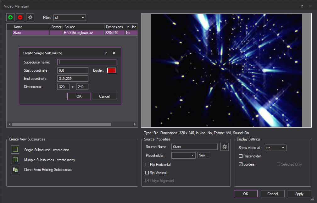
- Type the subsource name.
- By default, the system uses the start and end
coordinateds of the selected source, but you can change these values
as desired. When you change these values, the system automatically
updates the dimensions:
- Start Coordinate:
Type the starting coordinate for the subsource (the top-left corner
of the subsource) in the format “x,y”, where x is the horizontal coordinate
and y is the vertical coordinate. Note that the coordinate system
uses the top-left corner as the origin (0,0). also note that when
video is shown at 100-300%, a tooltip appears under the cursor, indicating
its position.
- End Coordinate: Type
the ending coordinate for the subsource (the bottom-right corner of
the subsource) in the format “x,y”, where x is the horizontal coordinate
and y is the vertical coordinate. Note that the coordinate system
uses the top-left corner as the origin (0,0).
- Click the Border box
to specify the color of the border that will appear around the subsource
when displayed.
- Click OK.
To create multiple video subsources
- In the left pane of the Video
Manager, click to highlight the video for which you want to
create subsources.
- In the bottom left corner of the window, click
Multiple subsources - create many.
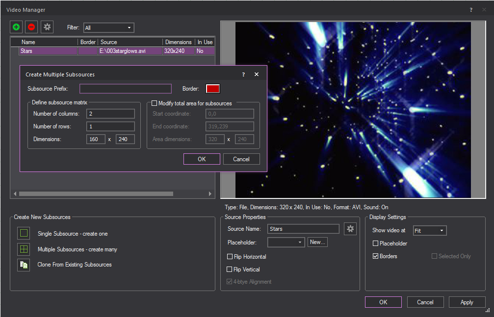
- Type the subsource name.
- Define the subsource matrix by specifying the
number of columns and rows. The dimensions of the subsources are displayed
for your reference:
- Number of columns:
Type the number of columns of subsources to be generated. If the video
resolution cannot be equally divided by this number, the remaining
pixels will be left at the end (for the horizontal pixels this means
the ones at the far right, and for the vertical pixels this means
that ones at the bottom.).
- Number of rows: Type
the number of rows of subsources to be generated. If the video resolution
cannot be equally divided by this number, there will be a few gaps
in the generated subsource grid.
- By default, the subsources are created by taking
the overall source area (height & width and evenly dividing it
by matrix provided. However, you an modify the total area by changing
the start/end coordinates and, therefore, the overall dimensions used
to create the subsources. to do so, select the checkbox beside Modify total area for subsources, and then enter
the appropriate values:
- Start Coordinate:
Type the starting coordinate for the subsource (the top-left corner
of the subsource) in the format “x,y”, where x is the horizontal coordinate
and y is the vertical coordinate. Note that the coordinate system
uses the top-left corner as the origin (0,0). also note that when
video is shown at 100-300%, a tooltip appears under the cursor, indicating
its position.
- End Coordinate: Type
the ending coordinate for the subsource (the bottom-right corner of
the subsource) in the format “x,y”, where x is the horizontal coordinate
and y is the vertical coordinate. Note that the coordinate system
uses the top-left corner as the origin (0,0).
- Click OK.
Result: The following graphic shows a video with nine
subsources (three columns and three rows).
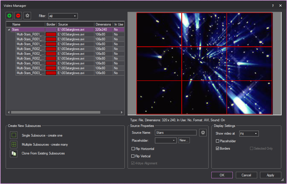
Notes:
- Subsources are always listed below the source
from which they were created.
- The table in the Video Manager provides
a convenient way of displaying source/subsource information; all sources
and their subsources are grouped, and can be expanded/collapsed.
- You can rearrange the columns in the table by
clicking the column header and dragging it to the new position.
- You can adjust the width of columns by clicking
the column border and dragging the column to its new width.
To clone an existing subsource to a new video
- In the left pane of the Video
Manager, click to highlight the video you want to clone a subsource
to.
- In the bottom left corner of the window, click
Clone From Existing Subsources.
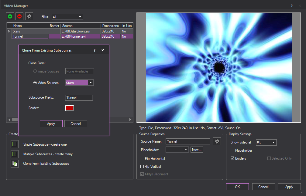
- Select the media type that contains the subsource
you want to clone, either Image Sources or
Video Sources.
- Select the desired subsource from the corresponding
source drop-down menu.
- Enter a name for the cloned subsource in the Subsource Prefix field.
- Click Apply.
Result: The selected subsource will be cloned and
applied to the 60 selected video.
Changing the properties of video sources and subsources
Note: If you change the source after the subsources
were created, and the new source has different dimensions that do not
match the subsources dimensions, the affected subsources are highlighted
in yellow (and a dialog appears to notify you as such).
When you select a row in the Video
Manager table, the properties of the video source or subsource
are displayed in the Source Properties section
of the window. You can change various properties of the video source and
subsources as follows:
- To change the border color of video subsources,
in the table, click the appropriate border color and then click on
the drop-down box that appears to select the new color. Click Update.
- To change the name of the video source or subsource,
in the table, click the appropriate row. Type the new name, and then
click Update.
- If you have already applied a video to multiple
objects, and then you want to replace the source file with something
different, you can make the change once in the Video
Manager and have it automatically applied to all related
objects (i.e., you don’t have to individually apply the changes to
each object's properties). To do so, you change the underlying source
file to the Video name.
- You can define a subsource either by its start/end
coordinates or by its dimensions:
- To resize the subsource, click the appropriate
row in the table. Change the start/end coordinates as desired, and
then click Update. Note that if you change
the coordinates, the system updates the dimensions automatically.
- To change the dimensions of a subsource, click
the appropriate row and then type the new dimensions. Note that when
you change the dimensions, the system will automatically add to the
start coordinate to determine a new end coordinate. Click Update.
Note: You can use the Video
Tool to apply the Video Subsources. For details, “Using
the Video Tool”.
To configure a new video source
for streaming video
To create a new video source for streaming
video, you use the Video Manager. There are
a couple of ways of opening the Video Manager (for
example, from the New Screen window, or from the menu);
the following procedure lists one possible way.
- From the .
- Click the New icon
in the upper-left corner.
Result: The Video Source
window opens.
- In the Name box, type
a descriptive name for the video.
- To play a video from a file, click the Video File option button, and then click
Browse to locate the file.
- To capture a live video stream from an external
source, such as a web cam or a video capture device that is attached
to your computer, click Video Capture,
and then use the drop-down arrow to select the appropriate device.
Vivien will detect what standard resolutions the capture device can
support, and display them in the Resolution drop-down
box; click this drop-down to choose your preferred resolution.
If you select a Video
Capture option, configure the Input and
Resolution values for the device:
- Input: Choose
between various inputs found on video capture devices (e.g., HDMI,
DVI, S-Video, and so on).
- Resolution: Select
the resolution of the incoming video, provided that multiple resolutions
are available from the selected input.
Note: The Video
Capture option must not be used when a Blackmagic Design video
capture device is used; when using such devices, you must click the next
option, Video Capture with Blackmagic Design Device.
Devices from manufacturers can only be detected and used if their driver
is of the WDM (Windows Driver Model) type. In order for Vivien to be able
to connect to the video capture device, that device must not be currently
in use by another application.
- A Blackmagic Design Device is automatically detected
in Vivien. The Video Capture with Blackmagic
Design Device radio button is automatically selected if
a Blackmagic Design Device is detected. A text prompt appears below
the Video Capture radio button confirming
the detection and asking to select the Blackmagic Design Device. Use
the drop-down box to select the Blackmagic Design Device.
Note: As
with all other capture devices, in order for Vivien to connect to Blackmagic
Design devices, that device must not be currently in use by another application.
- To play a view of a drawn Camera, click Camera (I-Mag) and select the Camera from
the drop-down.
- To mute the sound of the video, in the Video
Manager table, select the checkbox in the Mute column. If this checkbox is not selected,
the video’s sound will play.
- Click OK. If the video
is available, it connects automatically.
- Click OK to save
your changes and close the Video Manager.
Applying
textures
Vivien includes textures that simulate
various types of surfaces, such as brick or cloth. You can apply textures
to different objects, such as surfaces (created with the Surface tool
or by extruding a line), drape lines, library objects, and venues. You
can also use your own bitmap or jpeg files as textures, to simulate projection
screens, or to cover a surface with a texture specific to your event.
Vivien supports Alpha Mapping with PNG
images. Camera view can look through and lighting beams can pass through
transparent sections of these images.
Alpha Level supports Alpha Blending for
Camera on overlapping surfaces with transparency. Two overlapping translucent
surfaces will be displayed accurately showing the levels of intersecting
transparencies.
When customizing an object, you can apply
either a color or a texture;
you cannot apply both.
Note: You can apply textures in Vivien only if you
have installed them; in most cases, they are automatically installed with
the Vivien software.
To apply a texture
to a surface
The following procedure details how to
apply a texture to a surface, but it can also be used to apply a texture
to other objects by right-clicking, and then selecting .
- Right-click on the surface to which you want to
apply a texture, and then choose .
- Click the Appearance tab.
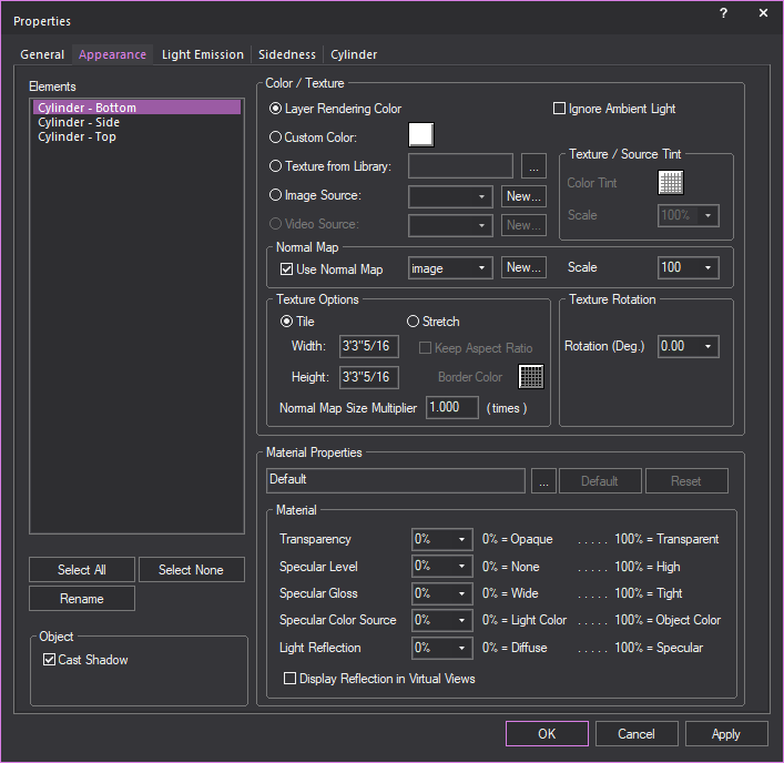
- Select the texture option that you want. The options
are:
- Texture from Library:
Indicates that the selected surface is a texture from the Vivien library.
The texture name appears in the box provided. Click the ellipsis button
(...) to modify the selected surface.
- Image Source: The
selected surface uses a texture from an external bitmap or jpeg file
on your hard drive rather than one from the Vivien library. Click
the ellipsis button (...) to select the external file to be used as
a texture.
- Video Source: This
option is only available for objects with the screen element such
as projection screens, TV screens, etc. The selected screen element
applies the texture from a live or pre-recorded video source. Click
on the drop-down menu to select from the images stored and available
in Video Manager, or click New
to create a new video source in the Video Manager.
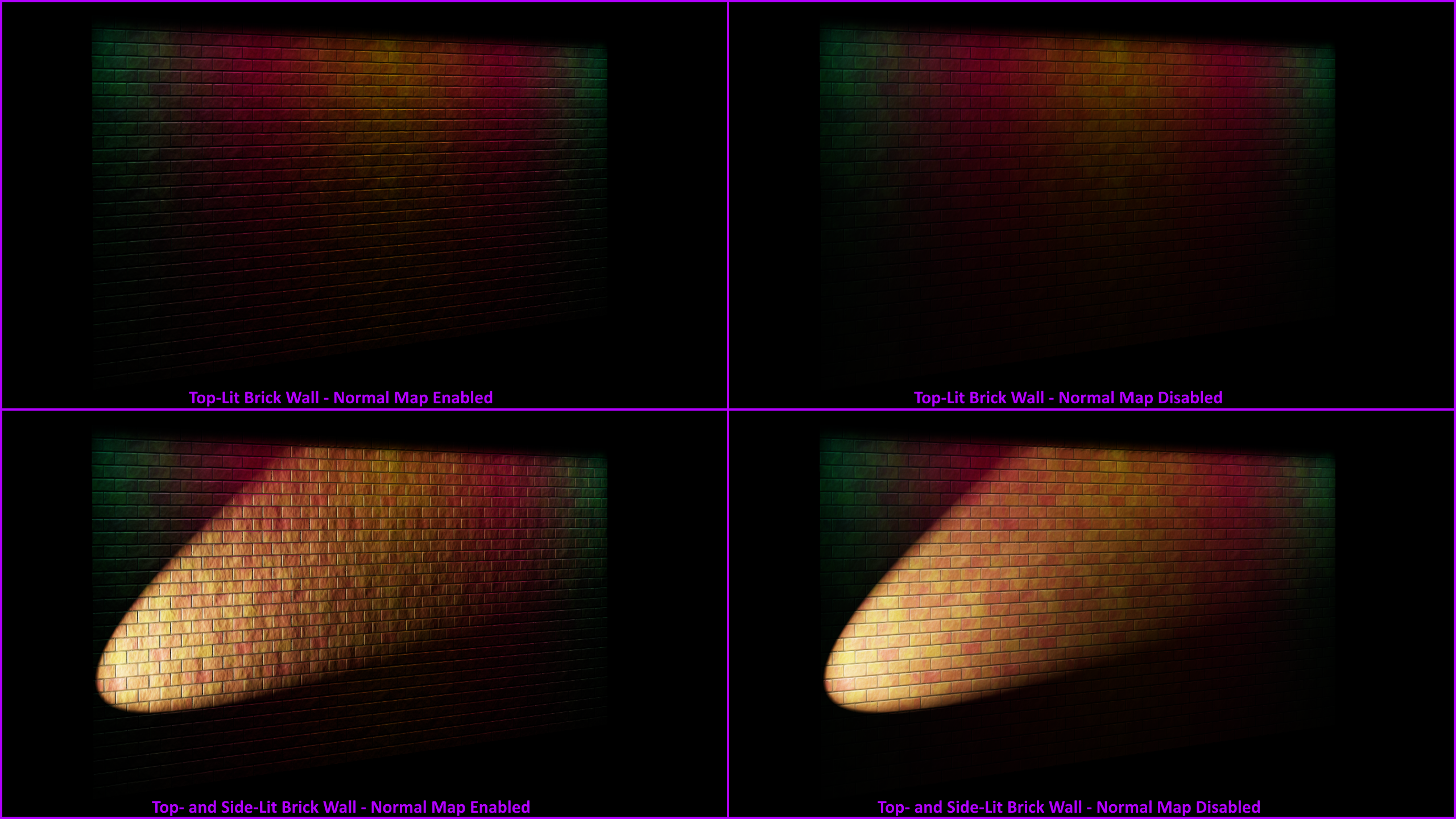
- Use Normal Map: The
selected surface uses an Image Source that’s a Normal Map, to create
the perception of fragmented surface texture detail and depth, making
objects look more realistic.
Click the drop-down box to apply an existing
Normal Map image or click New to create
a new Normal Map image via the Image Manager.
Note: This
drop-down lists all Image Sources that appear in the Image
Manager; as such Image Sources which are Normal Maps should be
named appropriately, for easy identification.
Click the Scale drop-down
box to set the height or depth of visual effect created by the Normal
Map. Click the drop-down box to select the percentage scale value from
not visible (0%) to maximum value stored in the imported Normal texture/image
(100%).
- Select Tile to
have the texture repeated over the selected element in a continuous
series of squares or rectangles, and then type the size of the frame
in which you want the texture to appear in the Width and
Height boxes. Based on the size that
you enter, Vivien calculates how many times the texture is repeated
(or tiled) to completely cover the selected element.
OR
Select Stretch to
make the selected texture grow to cover the entire surface. Based on the
aspect ratio and the rotation angle, Vivien evaluates the surface with
all of its edges and stretches the texture so the best fit is used. This
option is not active unless you choose a texture.
Tip: To preserve the aspect ratio of the texture
so it is not distorted when stretched over the surface, click Keep
Aspect Ratio.
- To choose a custom border color for the texture
when it is stretched over the surface, click the Border
Color box, and then choose the custom color.
- If you selected Use Normal
Map, you can specify the number of times the Normal Map is
multiplied across an object (element) to which it is applied. Type
the value in the Normal Map Size Multiplier box.
(Enter a valid number between 0.01 and 100.)
Note:
- The default value of 1 results in no changes
to the Normal Map’s size; values lower than 1 will increase the size
of the Normal visual effect, and values higher than 1 will decrease
it.
- The Normal Map Size Multiplier operates within the Tile or
Stretch Texture Options.
- If the texture has text or another recognizable
image in it, you might need to rotate the image to get it right-side
up. Type the rotation angle in the Rotation (Deg.) box.
- Click OK.
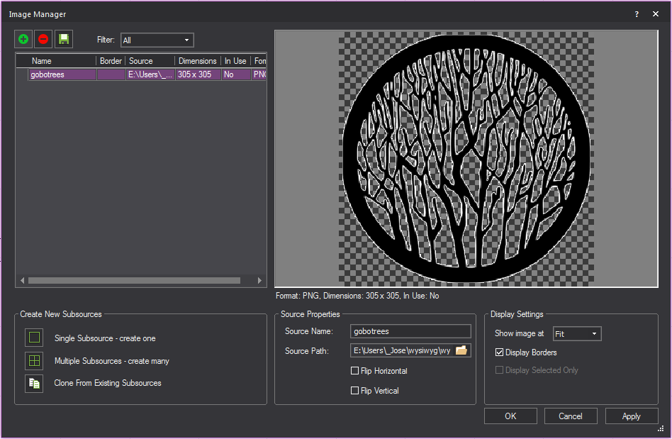
Applying textures with alpha
mapping
Vivien supports simple Alpha Mapping with
PNG images. Camera view can look through and lighting beams can pass through
transparent sections of these images that were set as textures.
Alpha Level supports Alpha Blending for
Camera on overlapping surfaces with transparency. Two surfaces with transparency
levels that overlap will be displayed accurately showing their transparencies
crossing each other
When Alpha Beam Shadows is enabled, alpha
fill percentage/value in images are utilized when altering the beam’s
color and intensity as it passes through surfaces with transparency. See
“Simulation
tab” in Virtual View options.
Beams do not handle different levels of
Alpha fill. Beams will only pass through the images with Alpha fill level
between 0 and 127 of 255.
In a PNG image file:
- Areas of the image filled with any level of transparency
will work correctly as transparent or semi-transparent textures in
Virtual View.
- Areas of the image filled with higher transparency
(Alpha fill level between 0 and 127 of 255) will allow beams to pass
through.
- Areas of the image filled with lower transparency
(Alpha fill level between 128 and 255) will not allow beams to pass
through.
Notes:
- Each alpha shadow level supported for this feature
requires additional video memory from your graphics card, which can
impact performance depending on your scene and computer hardware.
- Alpha texturing is supported with PNG images
containing alpha transparency build into the image. For more information
about using Alpha Textures, please see http://forums.cast-soft.com/index.php?threads/using-alpha-in-r38.662/.
- The Image Manager window
preview will display a grey checker pattern to identify the alpha
levels that are defined in the image.
Applying
textures with normal mapping
Normal Map images may be applied to objects
to make them appear three-dimensional without actually modifying their
geometry; the perceived visual effect is that of a fragmented surface
with high and low points that correctly interact with light.
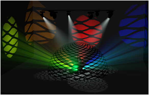
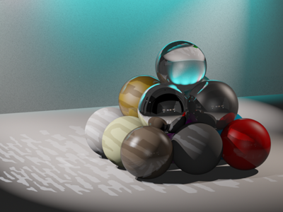
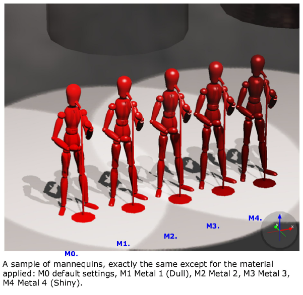
Applying materials
Materials differ from textures in that
they do not affect what the objects or surfaces look like, but rather
how they interact with light. The result of applying a material is only
apparent in renderings, as shown below.
Objects and surfaces can be assigned both
a texture and a material.
You apply materials using the Appearance tab
in the Object Properties
window. Vivien provides an assortment of materials from which you
can choose.
To apply a material to an object
- Right-click the object to which you want to apply
the material, and then choose .
Result: The Properties
window appears.
- In the Properties window,
click the Appearance tab.

- From the Elements
list box, choose the elements to which you want to apply the material.
To choose a custom material for the selected elements (such as metal,
paper, plastic, or fabric) click the ellipsis button (...) beside
the Material box.
Result: The Material Select
window appears.
Tip: When a material is highlighted in the Material Select window, a preview of the material
applied to objects is displayed.
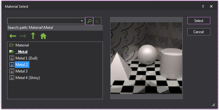
- In the Material Select window,
navigate to and highlight the desired material, and then click Select.
Result: The settings of the element will be configured
so that it simulates the material.
- If desired, you can edit the default properties
of the selected element. The element options vary as follows:
- Transparency: This
setting controls the proportion of light that passes through the material.
- Specular Level: This
setting controls how prominent other specular effects appear on the
material.
- Specular Gloss: This
settings controls the level of gloss a material will project.
- Specular
Color Source: This setting controls the color of light projected
on a material.
- Light Reflection:
This setting controls the amount of light that is reflected off the
material.
Notes:
- Use the drop-down menus to change any of the
material properties. Use the Reset button
to revert back to defaults.
- The beam will pass through a surface with the
Transparency value set to 80% or greater. The beam will not pass through
the surface when the value is lower than 80%.
- Click Apply.
- Click OK.
Material
reflections
The reflective properties of a material
can be toggled to enable true reflections in Virtual Views. When enabled,
the material will produce a detailed and faithful representation of everything
reflected on its surface.
Attention: The number of reflective material surfaces
that Vivien can support is 10.
When enabling reflections on an object, note the number of surfaces that
make up the object. For example, a cube has 6 sides. If an entire cube
was to be reflective, it would use 6 reflective surfaces.
To apply reflections to an object (surface object or venue)
Note: The quality of reflection is based on the
material properties of the object. Dull or unreflective materials will
reflect poorly.
- Right-click the object to which you want to apply
the material, and then choose .
Result: The Properties
window appears.
- In the Properties window,
click the Appearance tab.
- From the Elements list
box, choose the elements of the object which you want to apply the
reflection.
Note: Remember Vivien limits the number of reflective
surfaces to 10.
- In the Material Propertiessection, select the Display
Reflection in Virtual Views checkbox.
- Click Apply.
- Click OK.
- Go to Virtual View.
- Go to .
Result: the View Options window appears.
- In the View Options window, click the Simulation tab.
- Under the Materialssection, select the Enable checkbox.
- Select the Reflections
checkbox.
- Click OK.
Result: Reflective materials will be enabled and demonstrate
true reflections in Virtual View.
Applying a material to a library object element
You can apply different materials to each
element of Library objects using the Appearance tab
in the Properties window.
To apply a material to a Library object element
- Right-click the library object to which you want
to apply material, and then choose .
- Click the Appearance
tab.

- From the Elements list,
select an element.
- If a material was chosen previously, it is listed
in the Material Properties
box. To choose a different material, or to choose a material
for the first time, click the ellipsis (...) button, and then navigate
to the new material.
Note: Click Default to
remove your selection and apply the default material to the element.
- Repeat steps
4 and 5 for each element
to which you want to apply materials.
- When finished, click OK.
Quick Texture tool
You can apply the same texture and material
settings to multiple objects using the Quick Texture
Tool.
To use the Quick Texture tool
- From the Tools menu,
click Quick Texture.
Result: The
Quick Texture Settings window appears.
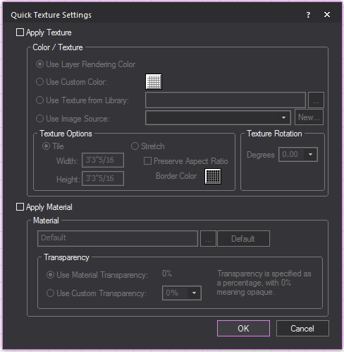
- To apply a texture, click Apply
Texture, and then select one of the following options: Use Layer Rendering Color,
Use Custom Color,
Use Texture from Library,
or Use
Texture from File. Complete the remaining texture options as
desired.
- To apply a material, click Apply
Material, and then select the material type by clicking the
ellipsis button (…). Specify the transparency to use default or custom
values.
- Click OK.
Result: The Quick Texture Settings window
closes and the Vivien workspace reappears. The cursor changes to a circle
with a Q symbol attached, indicating that you are in Quick Tools mode.
- Using your mouse, click on the object to which
you want to apply the texture/material settings.
Result: The Quick Texture
Tool’s element selection window appears.
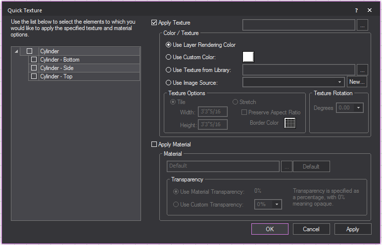
- From the list on the left, select the elements
to which you want to apply the texture/material settings.
- Optionally, with the elements selected, make any
last-minute changes required to your texture/material settings.
- Click OK.
Result: The texture/material settings are applied
to the object.
- Repeat steps
4 to 6 for as many
objects as desired.
- When you are finished, right-click and select
Finish Quick Tools