
Planning an event in Vivien involves creating a drawing of the venue, complete with all the staging, furniture, decor, A/V equipment, and so on required for the event.
Drawing in Vivien is like drawing in a CAD program, so many of the concepts will be familiar to those who have used a computer-aided drafting program before. Vivien has a comprehensive 3D library containing furniture, equipment, decor items and various human figures—everything you need to plan your event.
In this section
Adding Library objects to your drawing
In Vivien, you do all your drawing in the Drawing Wireframe tab or in the wireframe panes of the Drawing Quad tab.
Vivien drawings use a 1:1, or real scale. When you create a drawing in Vivien, you are generating a virtual representation of your real setup. If you were to do this on paper by hand, you would need to draw a scaled-down version of your space. Because there are no paper size limitations in the drawing wireframe views, you can draw your venue, tables, chairs, trusses, lighting fixtures, and so on in real scale.
You scale your drawing for printing purposes during print set-up and when creating Layouts for printing. The print settings allow you to print your drawings in whatever scales are necessary without having to redraw anything.
You can use either metric or imperial units for measurements.
You can also indicate whether you want:
Result: The Document Options window appears.
Whole: The measurements are rounded and displayed to the nearest whole number.
Fraction: The measurements are displayed to the nearest sixteenths of an inch, for Imperial, the nearest millimeter, for Metric.
You can change the measurement units on the fly by using the measurement units indicator on the Status bar.
While in any of the tabs, double-click the measurement units indicator (either Metric or Imperial) on the Status bar.
Result: The units instantly change to Metric or Imperial.
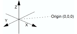
When drawing in Vivien Virtual Event Designer you are working in a 3D environment. Objects are drawn as 3D objects, with width, depth and height values based on the Cartesian coordinate system of 3 working axes—X, Y, and Z. The point where the 3 axes meet is called the origin and the values of X, Y, and Z are 0, expressed (0,0,0).
All objects in Vivien Virtual Event Designer occupy three-dimensional space. Different view types allow you to see and work with your drawing from different perspectives.
In Vivien Virtual View Event Designer, there are six types of wireframe views, each accessible from the View Type toolbar. Each of these views displays the working axes in different ways, as described below.
From the View menu, choose View Type and then select one of the following views:
 Plan
view
Plan
view
Plan views display the drawing from above looking down. This is similar to a plan view drawing on paper. In plan views, the working axes are X and Y and the Height value is Z.
 Left
view
Left
view
Left views display the drawing looking from the left side through the venue. This is similar to a section on paper. In left views the working axes are Y and Z.
 Right
view
Right
view
Right views display the drawing looking from the right side through the venue. This is similar to a section on paper. In right views the working axes are Y and Z.
 Front
view
Front
view
Front views display the drawing looking from the front side through the venue. This is similar to an elevation on paper. In front views the working axes are X and Z.
 Back
view
Back
view
Back views display the drawing looking from the back side through the venue. This is similar to an elevation on paper. In back views, the working axes are X and Z.
 3D view
A 3D view is a 3D perspective drawing. Although you view the drawing in the 3D perspective while in 3D view, you can only work in two axes. In 3D views, the working axes are dependent on the workplane selected.
The workplane selected determines the direction in which you can move your cursor in a 3D view. From the View menu, choose Workplane and then select one of the following workplanes:
 Workplane
Plan: The working axes are X and Y.
Workplane
Plan: The working axes are X and Y.
 Workplane Section: The working axes
are Y and Z.
Workplane Section: The working axes
are Y and Z.
 Workplane
Elevation: The working axes are X and Z.
Workplane
Elevation: The working axes are X and Z.
The crosshairs of your cursor change to reflect the selected workplane.
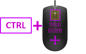
You can rotate the 3D view angle of the 3D view using your keyboard CTRL and arrow keys or CTRL keys and the third mouse button.
When using your mouse, you can also change the rotation speed when you increase or decrease the amount of pixels your mouse needs to travel to rotate the view on the screen using the CTRL keyboard and + or - keys in the keypad.
Hold down the CTRL key and tap the arrow keys on your keyboard.
OR
Hold down the CTRL key, and then click and drag the third mouse button (scroll wheel) towards the direction of the angle change.
Result: The 3D view angle of the 3D view changes according to the direction of the mouse movement.
Tip: If you add SHIFT to either method, the rotation slows down for both keyboard and mouse movement.
Notes:
Press and hold CTRL + SHIFT and tap the + keypad key (i.e. not the + at the top of the keyboard, by the DELETE key) to increase the number of pixels your mouse cursor needs to travel to rotate the view on your screen and slow down the view rotation.
OR
Press and hold CTRL + SHIFT and tap the - keypad key (i.e. not the - at the top of the keyboard, by the DELETE key) to decrease the number of pixels your mouse cursor needs to travel to rotate the view on your screen and speed up the view rotation.
Result:
Note: 20 pixels is the default number of mouse cursor travel distance.
Use your keyboard and mouse to control the point of view for any of the Vivien views and use the Zoom tools to shrink or enlarge the view on the screen.
Zoom tools allow you to view smaller or larger sections of a drawing. There are seven zoom tools available in Vivien.
From the View menu, choose one of the Zoom tools.
or
Use the Zoom tools on the View or Layouts View toolbars.
Result: The viewpoint is adjusted accordingly.
The available Zoom tools are listed in the following table:
Zoom tool |
Description |
|---|---|
Zoom In 
|
Moves your viewpoint closer to the center of the view. |
Zoom Out 
|
Moves your viewpoint farther away from the center of the view. |
Zoom Fit 
|
Adjusts the viewpoint so that the extremities of the drawing fit into the current view. |
Zoom Fit All |
For Quad views, adjusts the viewpoint so that the extremities of the drawing fit into the three wireframe views simultaneously. |
Undo View Change 
|
Adjusts the viewpoint so the most current changes to the view are undone |
Redo View Change 
|
Adjusts the viewpoint so that any changes to the view caused by Undo View |
Zoom Window 
|
Allows you to specify the area of the drawing to be viewed. For more information on using this tool, refer to the procedure below. |
Result: The view changes to amplify the area you selected.
Rotate tools allow you to shift 3D and Virtual Views left, right, up, or down.
In Vivien Designer, while in a 3D or Virtual View, from the View menu, choose Rotate View, and then choose one of the Rotate commands.
or
Use the Rotate tools on the View or Layouts View toolbars.
Result: The viewpoint is adjusted accordingly.
The available Rotate tools are listed in the following table.
Rotate tool |
Description |
|---|---|
Rotate View Left 
|
Moves your viewpoint to the left. |
Rotate View Right 
|
Moves your viewpoint to the right. |
Rotate View Up 
|
Moves your viewpoint up. |
Rotate View Down 
|
Moves
your viewpoint down. |
Action |
Key or mouse movement |
|---|---|
Move the view left, right, up and down |
Left, right, up and down arrow keys, respectively |
Zoom in and out |
PAGE UP and PAGE DOWN keys, respectively or Roll middle mouse button up and down. The zoom action is centered on the mouse pointer, not the center of the window. |
Rotate the view (3D perspective—3D or Virtual View only) |
Hold down the CTRL key and use arrow keys or PAGE UP and PAGE DOWN keys. |
Move the drawing around the window (pan)
|
Hold down the middle mouse button and drag. or Use the Pan tool
on the View toolbar. |
By default, Traditional Vivien is the camera control setting in the Virtual View where the mouse and keyboard action commands are standard Vivien commands used in all version of Vivien.
In the Application Options window, you can choose the Other 3D Applications on the Virtual View Camera Control drop-down list if you want to use camera control that comply with other 3D applications. See “Camera Control” for alternative mouse and keyboard action commands.
![]() © The CAST Group of Companies
Inc., 2004-2022 All rights reserved.
© The CAST Group of Companies
Inc., 2004-2022 All rights reserved.
